Home Blog Page 3

Refrigerant Piping Insulation

0
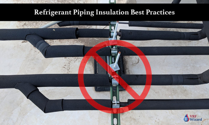
Refrigerant piping Insulation Best practices

Refrigerant piping insulation has historically escaped the scrutiny that it has found itself under recently in some jurisdictions. What could possibly be such a big deal with plain old boring refrigerant piping insulation? With energy codes getting stricter during each code cycle, and some large lawsuits related to refrigerant piping being improperly insulated, the need to get your insulation right is very important.

Whether you’re an owner or manager of a building or the installing contractor, you need to know how to protect yourself from litigation and costly mistakes due to the improper application of the code covering your project. This is not to be considered legal advice, but is for the purposes of bringing to light the need to discuss with your contractor or city officials the proper application of the code covering insulation.

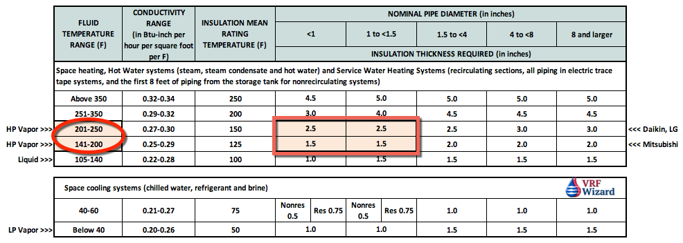
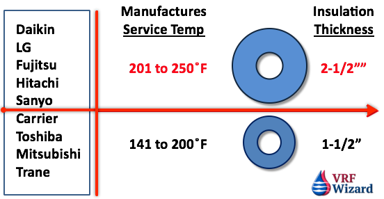
Each VRF/VRV manufacture has a different insulation requirement based on their operating temperatures. The biggest impact is for the High Pressure Vapor side of the requirements. Those VRF manufactures that have High Pressure Vapor operating temperature above 200 F would require 2-1/2” of insulation. I haven’t seen an installation with this thickness of insulation applied as mandated by the Building Energy Efficiency Standards.

ASHRAE, Energy Efficiency Standards & Code Requirements

OK, so what’s the big deal with VRF Insulation? Using the 2016 Building Energy Efficiency Standards in California or the IECC as our example, we will cover how confusing it can be to get the correct insulation specified on your project. You should review your model energy code or building codes for the requirements in your jurisdiction to see how they compare with this discussion.

We have replicated the 2016 Building Energy Efficiency Standards table 120.3-A Pipe Insulation Thickness below for this review, which matches Table C403.11.3 of the IECC (International Energy Conservation Code) and ASHRAE 90.1, Table 6.8.3-1

VRF Refrigerant Piping Insulation

Why do we Insulate Refrigerant Piping?

  • Maintain system capacity & efficiency. Avoid heat gains or losses.
  • Prevent condensation on piping or insulation.
  • Prevent piping system corrosion
  • Prevent mold growth from occurring on construction materials.
  • Avoid costly lawsuits.
  • Avoid property damage from condensation.

VRF VRV Operating & Design Temperatures

VRF manufactures have specified in their engineering and installation manuals temperatures that any insulation used on their system must be rated for. Many of the VRF/VRV manufactures have listed temperatures well above the operating temperatures of your normal VRF system. This has created a lot of confusion about which materials are acceptable and at what thickness.

If we look at table 120.3-A above we see that the thickness requirement changes when we get over 200 F. Some of the VRF/VRV manufactures have stated temperatures above 200 F, which would require insulation that is 2-1/2” thick. When is the last time you installed a project with 2-1/2” thick insulation on refrigerant piping for a VRF system? My guess is never.

VRF Manufactures Requirements

All VRV/VRF manufacturers (that we’re aware of) require the insulation to withstand at least 248˚F.

This 248˚F may be a manual reset, high-temperature safety limit on the high-pressure vapor (hot gas) line to protect the compressor or may be some other requirement from the manufacturer.

This is what dictates the need for EPDM insulation (yes, fiberglass and others can meet this, but EPDM is the only insulation that is a closed cell continuous vapor barrier).

This is not what dictates insulation thickness. If it was, all VRV/VRF manufacturer’s would require 2-1/2” on the high-pressure lines.

Important note: this also applies to the need for EPDM on insulated coils (line-sets) going to the fan coils.

To determine the VRF Refrigerant insulation requirements you will need to know several things to begin.

  • Which VRF manufactures system that you are using.
  • The pipe sizes.
  • What are the operating temperatures for the various refrigerant pipes.
    1. High Pressure Vapor
    2. Low Pressure Vapor
    3. Liquid Line

The peak normal operating temperatures are what dictate insulation thickness in accordance with current state energy codes and/or ASHRAE 90.1.

Peak normal operating temperatures for heat-recovery systems are as follows;

  • Carrier – 195˚F
  • Daikin – 239˚F
  • LG – 220˚F
  • Mitsubishi – 190˚F
  • Samsung – 190˚F
  • Hitachi – 220˚F
  • Trane – 190˚F

As can be seen, the temperatures for 3-pipe heat-recovery systems exceed 200˚F in normal operation

Important note: these temperatures also dictate the thicknesses needed on insulated coils (line-sets) going to the fan coils.

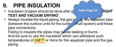
Daikin states in their VRV III Engineering & Installation manual on page 59 that pipe insulation is to be rated to with stand a temperature of 248 F. See insert below.

Daikin Refrigerant Piping Insulation Temp Rating

LG in their literature on page 37 calls for a temperature rating of 227 F.

LG Refrigerant Piping Insulation Temperature Rating

You can see that knowing the VRF/VRV manufactures requirement for the temperature rating of the insulation can have an effect on the thickness of the insulation required for the same size of pipe in the system. One VRF manufacture may require 1-1/2” and another 2-1/2” of insulation for the high pressure vapor piping.

Refrigerant Piping Insulation Thickness Requirements

It’s important that you check the VRF manufactures literature for the required temperature rating of the insulation, as each manufacture differs. Also, the VRF manufactures are dealing with contractors that have brought this issue to their attention, but as of this article have been slow to respond and make the appropriate corrections that limit the contractor or owners liability for differing from their published literature.

Most of us know that these thicknesses aren’t getting installed, as I’ve seen installations where the contractor just buys the standard pre-insulated line-set similar to these by Mueller. They have one thickness for both pipes, and don’t have one thick enough for most VRF manufactures requirements according to code. But somehow they never get flagged by inspectors for proper thickness or UV & weather protection compliance.

Insulation Material Temperature Ratings

  • Armacell (AP Armaflex) – Maximum Usage Temperature 220 F
  • NBR/PVC – Upper Use Limit  220 F
  • EPDM – Rated to 300 F (EPDM insulation systems utilizing adhesive and tape systems are rated to 257 F.)

Exterior Refrigerant Piping Insulation Protection

You will find that the CMC & IECC codes along with ASHRAE standards require that insulation installed on the exterior of a building be protected from the sun’s UV rays and the weather. Unfortunately we have all seen this one slip by the inspector’s watchful eye. One just has to look at the unprotected insulation that has been installed for several years to see the signs of degradation. The insulation will start to crack and come apart at the joints and seams.

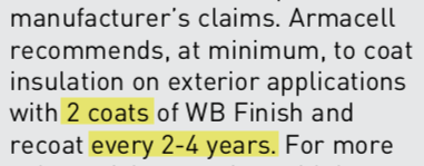
Armacell recommends that you coat their exterior insulation with 2 coats of WB Finish and re-coat every 2-4 years. I don’t know about you but I haven’t seen a lot of that being done. How many owners or management companies do you know that re-coat their insulation every 2 to 4 years? See armacell’s technical information bulletin on the “Outdoor Protection of Insulation”.

Armacell Insulation Exterior Applications

Examples of Poor Installation Methods

Here are a few examples of the improper application of insulation and what to avoid on your project.

If the wrong insulation is installed or if the installation is done improperly, you could end up with water damage to the building, or if a leak goes un-noticed you might get mold growing somewhere. That word sends shivers down the spine of owners and contractors, as it awakens the hungry lawyers. The integrity of your insulation will need to be maintained for the life of the mechanical system, so getting it right from the start is important. Invest in the proper insulation and installation procedures to insure that you have thermal & vapor integrity for the life of your system.

Attaching a Pipe Clamp Directly onto the Piping

Be sure to use inserts, saddles and shields where appropriate.
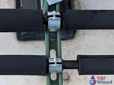
Pipe Insulation - Poor Installation - 1
Never attach directly to the Insulation with a pipe clamp.

Lack of UV Protection & Plastic Ties

obviously the owner or management company didn’t keep up with the continuous application of protective coating from the UV rays or the weather. Also the pipe clamps were incorrectly attached directly to the pipes.
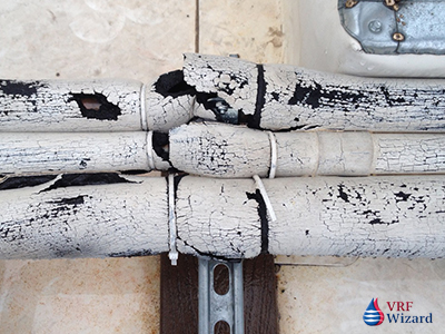
Piping Insulation - Poor Installation - 2
Brittle Insulation Lacking UV Protection with Plastic Ties

Missing Insulation

Not sure what happen here, but there isn’t much protection for the piping.
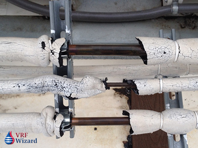
Piping Insulation - Poor Installation - 3
Missing Insulation

Lacking Piping Inserts

This installation didn’t even attach any portion of the piping or insulation to the unistrut support.
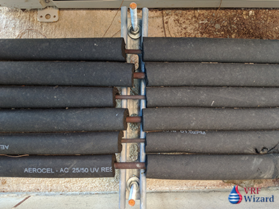
Piping Insulation - Poor Installation - 4
Lacking Pipe Inserts

Split Insulation – Bad Joints & Seams

The insulation is coming apart at the seams and joints due to poor application, and the improper insulation usage for an exterior application.
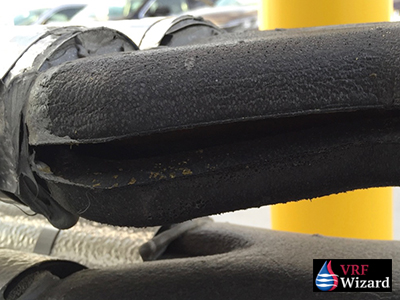
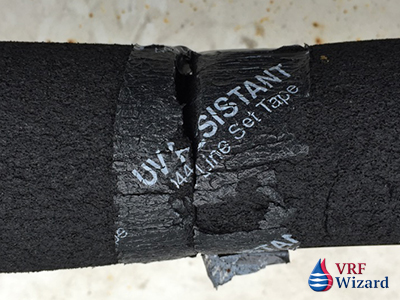
Piping Insulation - Poor Installation - 7
Split Insulation
Piping Insulation - Poor Installation - 8
Poor Insulation Joints & Tapes

Lack of Regulatory Enforcement and Knowledge

This opens up another discussion, and that is the awareness of the requirements and enforcement by the regulatory officials. I have found that from city to city or from one jurisdiction to another there is no consistency in enforcement. With the constant changing energy requirements that are being pushed to meet energy goals established by legislation or local authorities, and the updating of codes every three years, there is a need to remain vigilant. There are many improper installations that get approved and signed-off on which lack the proper installation methods, including the lack of UV & Weather protection for exterior refrigerant piping.

In defense of the regulatory officials, how are they to keep up with the wavering message about the temperature ratings of the insulation required by the various VRF manufactures.

How to reduce your Risk with Proper Installation Techniques

  • Use pipe inserts at Hangers/Attachments points to avoid insulation compression. Don’t clamp directly onto piping.
  • Use pipe saddles and shields to avoid crushing insulation. Be aware of pipe expansion and the possible movement of the saddle off the support. Fasten the saddle to the hanger and have a non-adhesive attachment to the pipe allowing it to move with the expansion. Make sure to use expansion loops where required.
  • Make sure all seams and joints are tightly sealed with contact adhesive.
  • Outdoor insulation should have UV and weather protection.
  • Don’t compress insulation as this will cause a loss of thermal efficiency and or surface condensation on cold pipes where compression occurs.
  • Leave space between insulated pipes.
  • Always use the correct size of insulation.
  • Make sure surface is clean, dry, unheated or uncooled.
  • Adhere insulation directly to the pipe every 12 to 18 feet, at the beginning and ends of run.
  • LEED projects require adhesives that have low to no VOC’s. Check the current version of LEED.

Piping Insulation Risk Profile

The risk related to the improper application or selection of refrigerant piping insulation can be represented in a simple graph. Your risk increases as your quality of installation varies from the manufactures recommendation, and as you deviate from the code requirements. To mitigate the risk requires that you use proper insulation and have it installed according to the manufactures requirements.
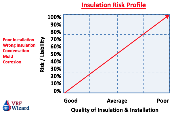
Refrigerant Piping Insulation Risk Profile Chart

Summary

It’s imperative that the installing contractor comply with all applicable codes and standards and manufactures recommended installation practices. Owners and property managers need to be aware of the maintenance requirements of any exterior insulation and the signs of a poor installation.

Inspectors have to be consistent in their application of the code and standards so that everyone is on the same playing field and the owner receives the protection that the insulation was designed to provide. VRV & VRF manufactures need to be consistent in their literature on the actual temperature requirements of the insulation for their systems.

Installers need to be sure that they meet the VRF manufacturers recommended temperature rating for the insulation they’re installing. It’s also imperative that they install the correct insulation, with the correct thickness, and one that meets the temperature rating and exterior protection requirements.


MEP Academy Online Courses
FREE HVAC Sheet Metal Courses Online

VRF Project Cost Tracker

0
VRF Project Cost Tracking 2

How Much does a VRF System Cost per Ton ($/Ton) or per Square Foot ($/Ft2)? How many Ft2/Ton should you figure? How much does the Electrical Cost per Indoor Unit ($/IDU)? Track all of these and MORE with the VRF Project Cost Tracker Spreadsheet.

Having a method to track the cost, engineering and installation metrics of a VRF/VRV Project will help you understand how to bid or budget these types of projects, along with what the typical project looks like. This VRF Project Cost Tracking Spreadsheet will help you understand the following and more:

  1. How much a VRF System cost per ton
  2. How much a VRF system cost per square foot
  3. How many square feet per ton a typical project in your area has.
  4. How much the VRF Equipment cost per ton.
  5. How much your ACR Refrigerant piping cost per linear foot installed.
  6. How many feet of piping can be installed in one man day.
  7. Lots more….

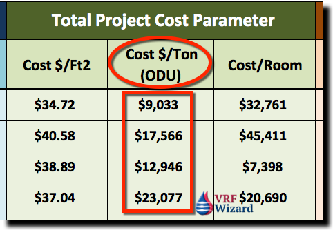
VRF Cost per Ton ($/Ton)

We believe one of the best ways to measure the cost of a VRF or VRV System is to keep track of the Total Cost per Ton for the different types of systems and the various options that effect its variability in cost. If you need to budget a VRF project quickly, there is no better method, followed by cost per square feet.

The VRF Project Cost Tracker Spreadsheet tracks dozens of other useful cost and engineering data.

VRF Project Cost Tracker
VRF Cost per Ton – VRF Project Cost Tracking Spreadsheet

In the above example, the wide spectrum of cost per ton is due to the total scope performed under each of the different VRF projects. Some projects include the cost to provide a turn-key project, meaning you will do all work associated with the installation of the VRF system in addition to the mechanical scope. Under a turn-key retrofit project you may need to pour concrete pads for your outdoor units or build equipment pads on the roof, provide electrical, general construction, etc. This is defined in the scope section of the spreadsheet.

VRF Cost per Ft2 ($/Ft2)

Another useful parametric to track is the cost per square foot to install a VRF system. If you know the square footage of the area that is being provided with a new VRF System, then you can track how much it cost per square foot to furnish and install the system. The below example would have the same cost variables as explained above for additional scope items. These are just examples not actual project values.

VRF Equipment Cost per Ton ($/Ton)

Another important factor to track is the cost per ton for purchasing just the VRF/VRV Equipment. You will want to use a spreadsheet to track the variables. The VRF Project Cost Tracking spreadsheet should be sortable per those variables for quick reference when doing budgets or checking a current bid or before purchasing VRF equipment.

VRF Equipment Price per Ton
VRF Equipment Price per Ton – VRF Project Cost Tracking Spreadsheet

Using the above project as an example, if your quoted equipment from your vendor for your Heat Recovery System was $150,000, we can then determine what we are paying per ton for this equipment.

  • VRF Equipment Cost $150,000
  • Total ODU (Outdoor Unit) Tonnage = 50 Tons
  • Cost per Ton = $150,000 / 50 Tons = $3,000/Ton

ACR Refrigerant Piping

The total footage required for each project varies based on several factors. One of those factors is the system type. VRF Heat Recovery Systems require more piping than VRF Heat Pump Systems. Then you have 2-pipe versus 3-pipe systems that can affect the total footage on VRF Heat Recovery Systems.

Tracking the total footage will help you understand how the piping affects pricing. We like to look at Linear Foot/Indoor Unit. This will give you a quick reference to how much pipe various projects require and how any project you are currently considering will be affected. (LF/Indoor Unit)

VRF ACR Piping Cost per Linear Feet
VRF ACR Piping Cost per Linear Feet – VRF Project Cost Tracking Spreadsheet

Piping (Linear Foot / Man Day) (LF/MD)

Another factor to consider that impacts cost and which is indicative of the risk of labor, is the productivity factor used for the installation of the ACR piping. The conditions imposed on each project for the installation of the ACR piping is different and is reflected in the overall productivity parametric.

In its basic unit of measurement, piping can be expressed in how many feet of pipe can one man install in a day (Linear Feet per Man Day). This is not to say that the project will only have one piping installer, but is an expression of the overall productivity of the piping crew expressed in its simplest form.

For example, if you had 4 individuals installing a total of 400 feet of ACR Piping and it took them a combined 64 hours, then you could express the total productivity of the 4-person crew in the parametric ‘Linear Feet per Man Day’, with the following calculation;

400 Feet / 64 Hours * 8 Hours/Day = 50 Feet / Day or (50 Feet per Man Day) 50 Ft/MD

Piping – Type of Joint

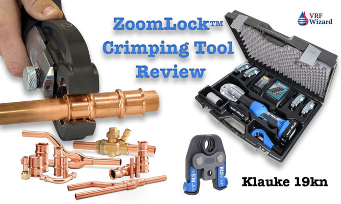
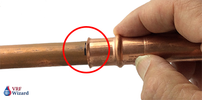
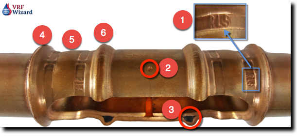
Another factor that you might want to note is the type of joint used that effects productivity. Using a ZoomLock Fitting which avoids brazing can save upwards of 60% of your labor, but your materials will cost more. You could also use Reftekk, which is a piping solution that uses bending soft or bendable copper tubing in lieu of brazing fittings.

This system can save you on labor, but will require the investment of the proper tools including a Swage Expander and Copper Bending Machine, along with the purchasing of the correct type of copper piping. There is another mechanical joint that avoids brazing called LokRing.

HVAC Sheet Metal

How many pounds of sheet metal does one project have compared to another, this will help you adjust for the differences. If your project has mostly wall mounted indoor units, then you won’t have much sheet metal ductwork.

If you’re using a lot of the concealed ducted indoor units or have a ducted outside air system then your project will show a cost impact for sheet metal.

If your company has a sheet metal fabrication shop, then you can put the cost of material and shop hours, if not, then you can just put the cost to purchase the material. Either way you should get the total pounds of sheet metal to help you budget future projects. Knowing the sheet metal cost per pound whether you fabricate or purchase it, will help you understand your cost and use it for budgeting.

VRF Sheet Metal Cost
VRF Sheet Metal Cost – VRF Project Cost Tracking Spreadsheet

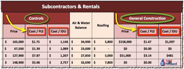
VRF Controls ($/Ft2)

All VRF/VRV Systems have some form of controls. Most of the VRF equipment is daisy-chained together with 16 or 18ga communication wire, while the main controllers require line voltage.

This section of the spreadsheet tracks the cost per square foot and cost per IDU (Indoor Unit) for the controls.

VRF Subcontractors and Rentals
VRF Subcontractors and Rentals – VRF Project Cost Tracking Spreadsheet

In addition to the VRF manufactures required wiring, the owner may have a requirement for BACnet capabilities or the ability to be controlled or viewed from their existing Building Automation system.

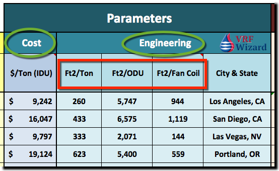
Total VRF Project Cost & Engineering Parameters

VRF Engineering Parameters
VRF Engineering Parameters – VRF Project Cost Tracking Spreadsheet

Ft2/Ton

Since you have been recording all the projects that you bid or are involved in, you have information on how many tons a certain type of building has per square feet. If the owner tells you he has a school in Los Angeles, California, then you can filter your spreadsheet for schools and determine from past projects approximately how many square foot per ton is required.

This isn’t scientific, but with experience and some handy data you can make an educated decision on the best Ft2/Ton value to use for your project. You can qualify your budget being based on a certain Ft2/Ton, and if the cooling calculations later determine something different, you’ll adjust your budget accordingly.

Ft2/Outdoor Unit (ODU)

This is an interesting parameter, as it measures how many square feet the design covers per Outdoor unit.

Ft2/Indoor Unit

This is an interesting parameter, as it measures how many square feet the design covers per Indoor unit.

VRF Project Bid Results

Keeping track of the winning bid, will help you stay abreast of market values.

  • How much did the project sell for?
  • How much per ton or per square foot did it sell for compared to what you figured?
VRF Bid Results
VRF Bid Results – VRF Project Cost Tracking Spreadsheet

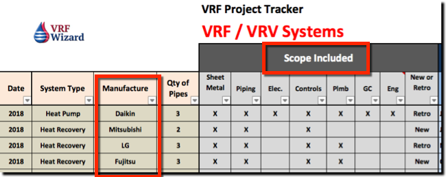
Scope Included

The VRF Project Cost Tracking Spreadsheet will help you quickly sort for projects that are similar in scope to the one you may need to budget or bid. Just check the boxes for the scope included. Everything from Sheet Metal, Piping, Electrical, Controls, Plumbing, General Construction, Engineering and if the project is for Retrofit or NEW Construction. This section

VRF Scope
VRF Scope Included – VRF Project Cost Tracking Spreadsheet

VRF Manufacture

Knowing the manufacture allows you to quickly sort for all the projects containing Mitsubishi, Daikin, LG, Fujitsu, Carrier, or any of the others.

System Type

Tracking the type of VRF systems, whether Heat Recovery or Heat Pump is important as they one has more components then the other which effects cost.

General Construction

Some renovation projects may require the mechanical contractor to provide a turn-key proposal. This is a proposal that covers the cost of all trades and services to complete the full scope of work required to install a new VRF/VRV system. This work will often require you to pour concrete pads for the outdoor units, remove and replace ceilings to hang indoor units, paint walls, etc.

VRF Project Information

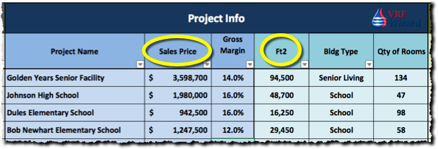
This section tracks the Project Name, Sales Price or Bid Price, Gross Margin %, FT2, Building Type & Quantity of Rooms.

VRF Project Info
VRF Project Info – VRF Project Cost Tracking Spreadsheet

VRF Equipment Cost Variables

System Diversity Factor

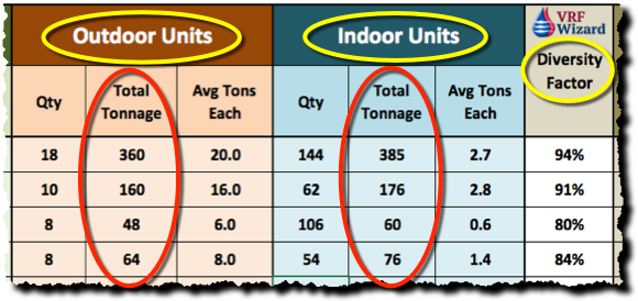
Tracking Diversity Factor will help indicate between projects being compared whether one has a greater diversity factor. This would indicate that one project has more Indoor Unit Tons to Outdoor Unit Tons then the other. Diversity allows you to use less Outdoor Unit Tonnage then Indoor because not all of your Indoor Units will require cooling or heating at the same time. Each zone or Indoor Unit will have a different time of month and day at which they will hit their peak load.

Tracking the quantity of main controllers and adapters or other control components that increase the cost of one project compared to another. One project may require more controllers and the capability to connect to an existing or new BAS system with BACnet capabilities.

VRF Outdoor and Indoor Unit
VRF Outdoor and Indoor Unit – VRF Project Cost Tracking Spreadsheet

Diversity Factor

This factor indicates the capacity of the Outdoor Units to the Indoor Units. A percentage below 100%, indicates that the Total Tonnage of the Outdoor Units is less than the total tonnage of the Indoor Units. The reason that the Outdoor Units usually total less that the total of all the Indoor units is because that the Indoor Units are sized for their PEAK LOADS. The diversity factor indicates that the Indoor Units will not all peak at the same time, so there is no need to size the Outdoor Units to handle the peak load. The Outdoor Units are sized to handle the block load.

Budgeting with the VRF Project Cost Tracker Spreadsheet

Below is an example on how you can quickly budget a VRF project using the VRF Project Cost Tracking Spreadsheet.

EXAMPLE #1

Information Given: 30,000 Ft2 Office, Single Story

STEP #1 (Determine Tonnage)
Determine Tonnage Using VRF Project Cost Tracker Spreadsheet (Engineering Data);

30,000 Ft2 / (500Ft2/Ton) = 60 Tons

STEP #2 (Determine Cost based on $/Ton)
Determine Sells Price using the VRF Project Cost Tracker Spreadsheet;

60 Tons x $15,000/Ton = $900,000

STEP #3 (Determine Cost based on $/Ft2)
Determine Sells Price using the VRF Project Cost Tracker Spreadsheet;

30,000 Ft2 x $29/Ft2 = $870,000

Price Range $870,000 to $900,000

When you keep track of all the information in a VRF spreadsheet, doing budgets and checking bid prices becomes a quick and easy task, saving you time and money. The examples here are simplified, as you would make sure the values you use match the comparable project as close as possible.

The above are just examples are not to be used for actual project pricing.

Who is this VRF Project Cost Spreadsheet for?

If you are a Contractor, Engineer, Distributor or Consultant that has anything to do with VRF/VRV system, then this spreadsheet is for you. By keeping track of the various cost that impacts a VRF/VRV project you will be able to provide quick budgets, do sanity checks for current VRF project proposals, track the cost per ton of VRF equipment and compare the variables that effect these projects.

How do you quickly Budget VRF Projects?

How do you track VRF Project cost and engineering parameters?

Get YOUR VRF Spreadsheet Now >>> VRF Project Cost Tracking Spreadsheet.

Currently only $249.00 $149.00

Reftekk Piping

0
Reftekk Bendable Piping

Reftekk Integrated Piping Solutions

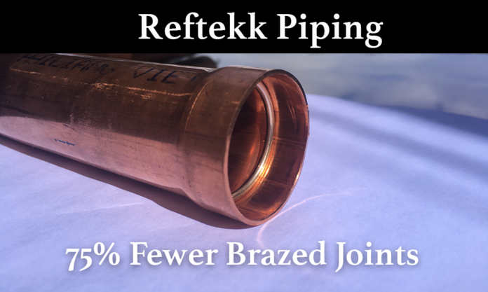
You may have heard of ZoomLock and LokRing for refrigerant pipe fittings, but have you heard of Reftekk? The Reftekk Bendable Piping Solution is another way to reduce installation labor for Refrigerant piping in a VRF system. Is it possible to eliminate up to 75% of the brazed joints using Reftekk Bendable Piping?

Reftekk piping uses bendable copper to eliminate some of the fittings in a refrigerant system. You will need to use soft (annealed, O60 or R220 Temper) or bendable quality (H55 or R250 Temper) copper tubing. It’s not to be used with hard (H58 Temper) copper tubing.

Reftekk Digi-Bender

You can bend up to 190 degree angle with the use of the Reftekk Digi-Bender. It’s easy to make precise bends by just scrolling the control wheel until the LED display shows the exact angle you want. Pull the trigger and the machine automatically bends your tube to the required angle set by you. (See Video demonstration below)

Reftekk Digi Bender
Reftekk Digi Bender

The Reftekk Digi-Bender will bend the following sizes of ACR Type-L copper tubing; 5/8”, 3/4”, 7/8”, 1-1/8”, and 1-3/8”. For the smaller sizes 1/4”, 3/8”, and 1/2” they recommended using the Imperial 370-FH copper tube bender.

Other approved tube benders include the REMS Curvo and the REMS Curvo 50

Reftekk Piping Degi Bender
Reftekk Piping Degi Bender LED Display

No More Elbows

There is no need for elbows when you use the Reftekk bendable copper system. By avoiding elbows you save time and money. With fewer elbows there are fewer brazed connections, thereby eliminating additional sources of leaks. For each fitting avoided you save at least two brazed joints.

If you need to make a tight turn then you might be forced to use a conventional fitting as the Reftekk Digi-Bender uses a long radius bend. This longer radius is beneficial for lower pressure drops, so it’s in your best interest to avoid tight turns.

ACR-L Bendable Copper Tubing

The Reftekk copper tubing is bendable and swageable which per the manufacture can eliminate up to 75% of the brazes in a typical system. That can add up to a lot of saved time and money. There is no need to lug around boxes of fittings when you can make your own out of the straight length bendable copper tubing.

One of the differences with the bendable version of this copper tubing is that it comes standard in nineteen (19) foot lengths instead of the traditional 20 foot sections. The ends of the tubing come plugged to keep the inside clean.

Reftekk Brazing Ring

The Reftekk bendable copper tubing comes in the following sizes; 1/4”, 3/8”, 1/2”, 5/8”, 3/4”, 7/8”, 1-1/8”, 1-3/8”, 1-5/8”, and 2-1/8”

Reftekk Swageable Copper

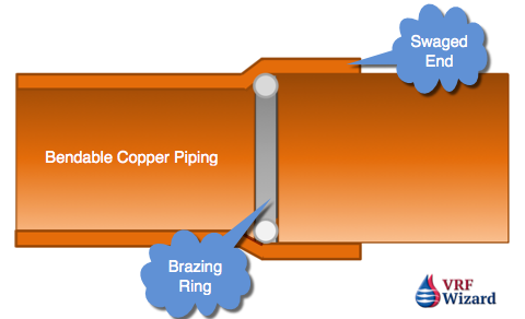
The Reftekk bendable copper tubing is capable of having a swageable connection applied to the ends to avoid having to use couplings. This will reduce the amount of fittings and brazed joints required, eliminating additional leak points and saving you time and money. By avoiding the use of a coupling which requires two brazed connections, you immediately eliminate 50% of the joints required. Less time preparing, purging and brazing.

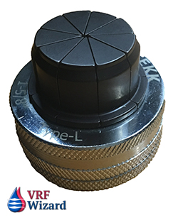
Reftekk Swage Expander

The swage is made with the Reftekk SwageX swaging expander which provides the correct swage depth on the end of any bendable quality copper tubing lengths. (See Video demonstration below)

Reftekk Swage Expander Head

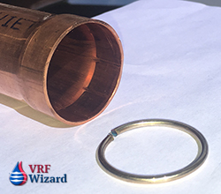
Reftekk ACR Brazing Rings

The Reftekk swageable copper tubing uses an internal brazing ring that you insert into the end of the swaged copper tube before brazing. This method provides brazing from the inside-out, as the brazing rings sits at the bottom of the swaged joint. When the joint is heated you will get a visual cue that the joint is complete when you see the brazing ring material penetrate the full depth of the swage and appear on the full circumference of the outer surface. The visual cue helps to prevent you from overheating the joint.

Reftekk Piping Brazing Ring

There is no guessing on how much filler material to use when you use the Reftekk ACR brazing rings, as each brazing ring is made to provide the correct amount of material for the joint. No longer do you have to keep hand feeding a brazing rod while wondering if you have the correct amount to make a leak proof joint.

The Brazing ring is comprised of approximately 15% silver, 5% Phosphorus and the rest copper. The melting point of the Reftekk Brazing ring is at 1190 F and flows at 1300 F.

Reftekk Piping Brazing Ring

There is no flux needed with the Reftfekk Brazing Rings as the rings have Phosphorus flux built into them. Reftekk recommends that you use Oxy-Propane instead of Oxy-Acetlyne.

The Reftekk ACR Brazing Rings come in the following sizes; 3/8”, 1/2”, 5/8”, 3/4”, 7/8”, 1-1/8”, 1-3/8”, and 1-5/8”.

Refrigerant Ball Valves

Reftekk provides refrigerant ball valves with an optional EPDM insulation jacket in sizes ranging from a 1/4” to 2-1/8”. These ball valves swaged connections that accept the same brazing rings as the pipe tubing. There is a schrader valve built into the brass body of the refrigerant ball valve for easy access. The valve has a maximum working pressure of 700 psig and a working temperature range from -40F to 300F (-40C to 150C).


Summary

With up to 75% fewer brazes the Reftekk Integrated Piping Solution is a great option to the standard use of fittings, helping you to save time and money while reducing the amount of joints that could potentially leak. You will still need to prepare the joint and purge with nitrogen, but you will have less joints to make. I believe Reftekk can save you time and money and should be something that you offer your customers.

Checkout their mobile bender application that makes bending copper easy and for which they won the 2020 Dealer Design Award from ARCHR News.

Check out this Reftekk Piping Flyer.

Check out these other types of Piping Connections & Tool Reviews;

  1. ZoomLock
  2. SmartLock Fitting
  3. LokRing
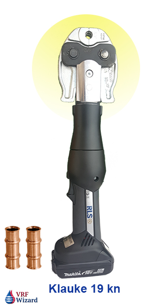
  4. ZoomLock Tool Review
  5. ZoomLock Cost Analysis
MEP Academy Online Courses
HVAC Sheet Metal Courses Online

Mitsubishi VRF Hybrid System

0
Mitsubishi VRF Hybrid System

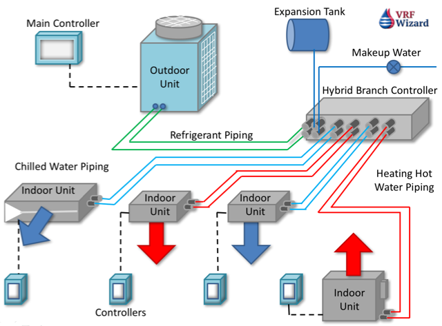
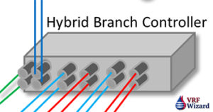
This Mitsubishi Hybrid VRF System is a Heat Recovery System that uses Refrigerant on the primary side of the branch controller box and water on the secondary side to the indoor units. This VRF system mixes the best of various technologies, VRF, Chilled Water & Heating Hot Water systems.

Within the Hybrid Branch Controllers are two heat exchangers for the transfer of heat between the primary refrigerant side and the water side. Also inside the Branch Controller are two DC inverter driven water pumps that circulate water from the Hybrid Branch Controller to the Indoor Units in a closed loop. This puts the heat exchanger, valves and pumps within the Hybrid branch Controller.

The Hybrid VRF system uses the same control and network setup as the conventional VRF system.

VRF Main Controller
VRF Main Controller

Without the use of refrigerant going to the indoor units, compliance with BS EN378, the standard used in Europe where this technology is currently available is similar to the standard used in the United States referenced as ASHRAE 15 & 34. These guidelines or regulations are meant to protect occupants from a possible refrigerant leak. Since only water runs to the indoor unit, there is no need for refrigerant leak detection.
The Mitsubishi Hybrid Branch Controller comes with 8 or 16 ports allowing up to 16 separate zones.

Mitsubishi Hybrid VRF Branch Controller

Inside the Hybrid Branch Controller you’ll find two heat exchangers at opposite ends of the box that each separates the refrigerant from the water side. These two heat exchangers operate in one of three modes.

  1. Both provide cooling.
  2. Both provide heating.
  3. Mixed mode. One provides cold water the other hot water.

Each heat exchanger has a DC inverter driven water pump that delivers water to the indoor unit from the Mitsubishi Hybrid Branch Controller. The branch controller contains the heat exchangers, pumps and the valves that provide directional flow, providing either cooling or heating.

VRF Hybrid System Advantages

  1. No leak detection required
  2. No refrigerant in occupied spaces. (This depends on where you put your Hybrid branch controller)
  3. High sensible cooling and stable room temperatures
  4. Hybrid VRF provides a 5% DECREASE in CAPEX cost vs VRF with Leak Detection
  5. Mitsubishi claims a 10% increase in sensible cooling vs VRF for this hybrid VRF.
  6. 2 Pipe design vs 4 Pipe (CHW & HHW)
  7. The use of plastic is allowed by the manufacture for the water side. This saves on the cost of copper and the additional labor for purging and brazing.
  8. Simultaneous heating & cooling
  9. Similar in terms of control & design flexibility
  10. Quite operation

You will need to add an expansion tank and makeup water line to the Mitsubishi Hybrid VRF Branch Controller.

Here is a video of the system available in various European countries and New Zealand

MEP Academy Online Courses
HVAC Sheet Metal Courses Online

VRF Project Video – The Mackie Building

0

A mixed use building in Downtown Milwaukee Wisconsin the Mackie Building is an 55,000 square-foot historic building complete with restaurants, businesses and residential spaces which is using the LG VRF system

MEP Academy Online Courses
HVAC Sheet Metal Courses Online

VRF Manufactures Equipment List

0
VRF Manufactures List

Enclosed you will find each VRF Manufactures Equipment List with links to their products for VRF Heat Pump and Heat Recovery systems. Carrier – Mitsubishi – Daikin


Carrier_VRFCarrier

Heat Pumps – Carrier (6 to 36 Tons)

carrier vrf heat pump

  1. Carrier Outdoor Unit 38 VMH (6 to 36 Tons) – Engineering Manual
  2. Carrier Outdoor Unit 38 VMH-1P (3 to 5 Tons) – Engineering Manual
  3. Carrier Outdoor Unit 38 VMH-1P (3 to 5 Tons) Single Phase 7-10-17

Heat Recovery – Carrier

  1. Carrier Outdoor Unit 38 VMR (6 to 28 Tons)
  2. Carrier Outdoor Unit 38 VMR – Engineering Manual

Heat Recovery Outdoor Units (6 to 28 Tons)

carrier vrf outdoor unit heat recovery

  1. Carrier Outdoor Unit 20-Tons (208-230/3/60) Large Cabinet
  2. Carrier Outdoor Unit 20-Tons (460/3/60) Large Cabinet
  3. Carrier Outdoor Unit 22-Tons (208-230/3/60)
  4. Carrier Outdoor Unit 22-Tons (460/3/60)
  5. Carrier Outdoor Unit 24-Tons (208-230/3/60)
  6. Carrier Outdoor Unit 24-Tons (460/3/60)
  7. Carrier Outdoor Unit 26-Tons (208-230/3/60)
  8. Carrier Outdoor Unit 26-Tons (460/3/60)
  9. Carrier Outdoor Unit 28-Tons (208-230/3/60)
  10. Carrier Outdoor Unit 28-Tons (460/3/60)
  11. Carrier VRF Outdoor Heat Recovery Installation Manual

Indoor Units – Carrier

4-Way Cassettes – Carrier

carrier vrf 4 way cassette

  1. Carrier Compact 4-Way Cassette 40 VMC (0.5 to 1.25 Tons) Engineering Manual
  2. Carrier 4-Way Cassette 40 VMF (0.75 to 4 Tons) Engineering Manual

Ducted VRF – Carrier

carrier vrf low static ducted

Low Static Ducted – Carrier

  1. Carrier Low Static Ducted 40 VML (0.5 to 2 Tons) Engineering Manual

Medium Static Ducted – Carrier

  1. Carrier Medium Static Ducted 40 VMM (0.5 to 4 Tons) Engineering Manual
  2. Carrier Medium Static Ducted 40 VMM (0.5 to 4 Tons) Installation

High Static Ducted (2 to 8 Tons) – Carrier

  1. Carrier High Static Ducted 40 VMH (2 to 8 Tons) Engineering Manual
  2. Carrier High Static Ducted 40 VMH (2 Tons) Submittal
  3. Carrier High Static Ducted 40 VMH (2.5 Tons) Submittal
  4. Carrier High Static Ducted 40 VMH (3 Tons) Submittal
  5. Carrier High Static Ducted 40 VMH (4 Tons) Submittal
  6. Carrier High Static Ducted 40 VMH (4.5 Tons) Submittal
  7. Carrier High Static Ducted 40 VMH (6 Tons) Submittal
  8. Carrier High Static Ducted 40 VMH (8 Tons) Submittal

Floor Console (0.5 to 4 Tons) – Carrier

carrier vrf floor console

  1. Carrier Floor Console 40 VMR (0.5 o 2 Tons) Engineering Manual
  2. Carrier UnderCeiling 40 VMU (1 to 4 Tons) Engineering Manual

Vertical Air Handler (1.5 to 4.5 Tons) – Carrier

carrier vrf vertical air handler

  1. Carrier Vertical Air Handling Unit 40 VMV (1.5 to 4.5 Tons) Engineering
  2. Carrier Vertical Air Handling Unit 40 VMV (1.5 to 4.5 Tons) Installation

High Wall (0.5 to 2.5 Tons) – Carrier

carrier vrf high wall

  1. Carrier High Wall 40 VMW (0.5 to 2.5 Tons) Engineering
  2. Carrier High Wall 40 VMW (0.5 to 2.5 Tons) Installation

Outdoor Air, Ventilation Unit – Carrier (3 to 8 Tons)

carrier vrf ventilation air unit

  1. Carrier Indoor Ventilation Unit 40 VMA (3 to 8 Tons) Engineering
  2. Carrier Indoor Ventilation Unit 40 VMA (3 Tons) Submittal
  3. Carrier Indoor Ventilation Unit 40 VMA (4 Tons) Submittal
  4. Carrier Indoor Ventilation Unit 40 VMA (4.5 Tons) Submittal
  5. Carrier Indoor Ventilation Unit 40 VMA (6 Tons) Submittal
  6. Carrier Indoor Ventilation Unit 40 VMA (8 Tons) Submittal
  7. Carrier Indoor Ventilation Unit 40 VMA (3 to 8 Tons) Installation

Multiport Distribution Controller – Carrier

carrier multiport distribution controller

  1. Carrier Multiport Distribution Controller 40 VMD (6, 8, 10, 16 Port) Engineering
  2. Carrier Multiport Distribution Controller 40 VMD (6, 8, 10, 16 Port) Installation
  3. Carrier Multiport Distribution Controller 40-006-016 VMD (16 Port) Submittal

Brochures – Carrier


Mitsubishi VRFMitsubishi

Heat Pump – Mitsubishi – Air Cooled (6 to 30 Tons)Mitsubishi VRF Heat Pump PURY_P00TLMU_A

  1. Mitsubishi Heat Pump 6 Tons PUHY-P72TLMU-A(BS) (208/230VAC)
  2. Mitsubishi Heat Pump 6 Tons PUHY-P72YLMU-A(BS) (460VAC)
  3. Mitsubishi Heat Pump 8 Tons PUHY-P96TLMU-A(BS) (208/230VAC)
  4. Mitsubishi Heat Pump 8 Tons PUHY-P96YLMU-A(BS) (460VAC)
  5. Mitsubishi Heat Pump 10 Tons PUHY-P120TLMU-A(BS) (208/230VAC)
  6. Mitsubishi Heat Pump 10 Tons PUHY-P120YLMU-A(BS) (460VAC)
  7. Mitsubishi Heat Pump 12 Tons PUHY-P144TLMU-A(BS) (208/230VAC)
  8. Mitsubishi Heat Pump 12 Tons PUHY-P144TSLMU-A(BS) (208/230VAC)
  9. Mitsubishi Heat Pump 12 Tons PUHY-P144YLMU-A(BS) (460VAC)
  10. Mitsubishi Heat Pump 12 Tons PUHY-P144YSLMU-A(BS) (460VAC)
  11. Mitsubishi Heat Pump 14 Tons PUHY-P168TLMU-A(BS) (208/230VAC)
  12. Mitsubishi Heat Pump 14 Tons PUHY-P168TSLMU-A(BS) (208/230VAC)
  13. Mitsubishi Heat Pump 14 Tons PUHY-P168YLMU-A(BS) (460VAC)
  14. Mitsubishi Heat Pump 14 Tons PUHY-P168YSLMU-A(BS) (460VAC)
  15. Mitsubishi Heat Pump 16 Tons PUHY-P192TSLMU-A(BS) (208/230VAC)
  16. Mitsubishi Heat Pump 16 Tons PUHY-P192YSLMU-A(BS) (460VAC)
  17. Mitsubishi Heat Pump 18 Tons PUHY-P216TSLMU-A(BS) (208/230VAC)
  18. Mitsubishi Heat Pump 18 Tons PUHY-P216YSLMU-A(BS) (460VAC)
  19. Mitsubishi Heat Pump 20 Tons PUHY-P240TSLMU-A(BS) (208/230VAC)
  20. Mitsubishi Heat Pump 20 Tons PUHY-P240YSLMU-A(BS) (460VAC)
  21. Mitsubishi Heat Pump 22Tons PUHY-P264TSLMU-A(BS) (208/230VAC)
  22. Mitsubishi Heat Pump 22 Tons PUHY-P264YSLMU-A(BS) (460VAC)
  23. Mitsubishi Heat Pump 24 Tons PUHY-P288TSLMU-A(BS) (208/230VAC)
  24. Mitsubishi Heat Pump 24 Tons PUHY-P288YSLMU-A(BS) (460VAC)
  25. Mitsubishi Heat Pump 26 Tons PUHY-P312TSLMU-A(BS) (208/230VAC)
  26. Mitsubishi Heat Pump 26 Tons PUHY-P312YSLMU-A(BS) (460VAC)
  27. Mitsubishi Heat Pump 28 Tons PUHY-P336TSLMU-A(BS) (208/230VAC)
  28. Mitsubishi Heat Pump 28 Tons PUHY-P336YSLMU-A(BS) (460VAC)
  29. Mitsubishi Heat Pump 30 Tons PUHY-P360TSLMU-A(BS) (208/230VAC)
  30. Mitsubishi Heat Pump 30 Tons PUHY-P360YSLMU-A(BS) (460VAC)

Heat Pump – Mitsubishi – Water Cooled (6 to 30 Tons)

  1. Mitsubishi Heat Pump 6 Tons PQHY-P72TLMU-A1 (208/230VAC)
  2. Mitsubishi Heat Pump 6 Tons PQHY-P72YLMU-A1 (460VAC)
  3. Mitsubishi Heat Pump 8 Tons PQHY-P96TLMU-A1 (208/230VAC)
  4. Mitsubishi Heat Pump 8 Tons PQHY-P96YLMU-A1 (460VAC)
  5. Mitsubishi Heat Pump 10 Tons PQHY-P120TLMU-A1 (208/230VAC)
  6. Mitsubishi Heat Pump 10 Tons PQHY-P120YLMU-A1 (460VAC)
  7. Mitsubishi Heat Pump 12 Tons PQHY-P144TLMU-A1 (208/230VAC)
  8. Mitsubishi Heat Pump 12 Tons PQHY-P144TSLMU-A1 (460VAC)
  9. Mitsubishi Heat Pump 12 Tons PQHY-P144YLMU-A1 (208/230VAC)
  10. Mitsubishi Heat Pump 12 Tons PQHY-P144YSLMU-A1 (460VAC)
  11. Mitsubishi Heat Pump 14 Tons PQHY-P168YSLMU-A1 (460VAC)

Heat Recovery Outdoor Units -Air Cooled (6 to 28 Tons)mitsubishi vrf outdoor unit air-cooled

  1. Mitsubishi Outdoor Unit 6-Tons PURY-P72TLMU (208/230VAC)
  2. Mitsubishi Outdoor Unit 6-Tons PURY-P72YLMU (460VAC)
  3. Mitsubishi Outdoor Unit 8-Tons PURY-P96TLMU (208/230VAC)
  4. Mitsubishi Outdoor Unit 8-Tons PURY-P96YLMU (460VAC)
  5. Mitsubishi Outdoor Unit 10-Tons PURY-P120TLMU (208/230VAC)
  6. Mitsubishi Outdoor Unit 10-Tons PURY-P120YLMU (460VAC)
  7. Mitsubishi Outdoor Unit 12-Tons PURY-P144TLMU (208/230VAC)
  8. Mitsubishi Outdoor Unit 12-Tons PURY-P144YLMU (460VAC)
  9. Mitsubishi Outdoor Unit 12-Tons PURY-P144TSLMU (208/230VAC)
  10. Mitsubishi Outdoor Unit 12-Tons PURY-P144YSLMU (460VAC)
  11. Mitsubishi Outdoor Unit 14-Tons PURY-P168TLMU (208/230VAC)
  12. Mitsubishi Outdoor Unit 14-Tons PURY-P168YLMU (460VAC)
  13. Mitsubishi Outdoor Unit 14-Tons PURY-P168TSLMU (208/230VAC)
  14. Mitsubishi Outdoor Unit 14-Tons PURY-P168YSLMU (460VAC)
  15. Mitsubishi Outdoor Unit 16-Tons PURY-P192TSLMU (208/230VAC)
  16. Mitsubishi Outdoor Unit 16-Tons PURY-P192YSLMU (460VAC)
  17. Mitsubishi Outdoor Unit 18-Tons PURY-P216TSLMU (208/230VAC)
  18. Mitsubishi Outdoor Unit 18-Tons PURY-P216YSLMU (460VAC)
  19. Mitsubishi Outdoor Unit 20-Tons PURY-P240TSLMU (208/230VAC)
  20. Mitsubishi Outdoor Unit 20-Tons PURY-P240YSLMU (460VAC)
  21. Mitsubishi Outdoor Unit 22-Tons PURY-P264TSLMU (208/230VAC)
  22. Mitsubishi Outdoor Unit 22-Tons PURY-P264YSLMU (460VAC)
  23. Mitsubishi Outdoor Unit 24-Tons PURY-P288TSLMU (208/230VAC)
  24. Mitsubishi Outdoor Unit 24-Tons PURY-P288YSLMU (460VAC)
  25. Mitsubishi Outdoor Unit 26-Tons PURY-P312TSLMU (208/230VAC)
  26. Mitsubishi Outdoor Unit 26-Tons PURY-P312YSLMU (460VAC)
  27. Mitsubishi Outdoor Unit 28-Tons PURY-P336TSLMU (208/230VAC)
  28. Mitsubishi Outdoor Unit 28-Tons PURY-P336YSLMU (460VAC)

Heat Recovery Outdoor Units -Water Cooled (6 to 26 Tons)

mitsubishi vrf outdoor unit water-cooled

  1. Mitsubishi Outdoor Unit 6-Tons PQRY-P72TLMU (208/230VAC)
  2. Mitsubishi Outdoor Unit 6-Tons PQRY-P72YLMU (460VAC)
  3. Mitsubishi Outdoor Unit 8-Tons PQRY-P96TLMU (208/230VAC)
  4. Mitsubishi Outdoor Unit 8-Tons PQRY-P96YLMU (460VAC)
  5. Mitsubishi Outdoor Unit 10-Tons PQRY-P120TLMU (208/230VAC)
  6. Mitsubishi Outdoor Unit 10-Tons PQRY-P120YLMU (460VAC)
  7. Mitsubishi Outdoor Unit 12-Tons PQRY-P144TLMU (208/230VAC)
  8. Mitsubishi Outdoor Unit 12-Tons PQRY-P144YLMU (460VAC)
  9. Mitsubishi Outdoor Unit 12-Tons PQRY-P144TSLMU (208/230VAC)
  10. Mitsubishi Outdoor Unit 12-Tons PQRY-P144YSLMU (460VAC)
  11. Mitsubishi Outdoor Unit 14-Tons PQRY-P168TLMU (208/230VAC)
  12. Mitsubishi Outdoor Unit 14-Tons PQRY-P168YLMU (460VAC)
  13. Mitsubishi Outdoor Unit 14-Tons PQRY-P168TSLMU (208/230VAC)
  14. Mitsubishi Outdoor Unit 14-Tons PQRY-P168YSLMU (460VAC)
  15. Mitsubishi Outdoor Unit 16-Tons PQRY-P192TLMU (208/230VAC)
  16. Mitsubishi Outdoor Unit 16-Tons PQRY-P192YLMU (460VAC)
  17. Mitsubishi Outdoor Unit 16-Tons PQRY-P192TSLMU (208/230VAC)
  18. Mitsubishi Outdoor Unit 16-Tons PQRY-P192YSLMU (460VAC)
  19. Mitsubishi Outdoor Unit 18-Tons PQRY-P216TLMU (208/230VAC)
  20. Mitsubishi Outdoor Unit 18-Tons PQRY-P216YLMU (460VAC)
  21. Mitsubishi Outdoor Unit 18-Tons PQRY-P216TSLMU (208/230VAC)
  22. Mitsubishi Outdoor Unit 18-Tons PQRY-P216YSLMU (460VAC)
  23. Mitsubishi Outdoor Unit 20-Tons PQRY-P240TLMU (208/230VAC)
  24. Mitsubishi Outdoor Unit 20-Tons PQRY-P240YLMU (460VAC)
  25. Mitsubishi Outdoor Unit 20-Tons PQRY-P240TSLMU (208/230VAC)
  26. Mitsubishi Outdoor Unit 20-Tons PQRY-P240YSLMU (460VAC)
  27. Mitsubishi Outdoor Unit 22-Tons PQRY-P288TSLMU (208/230VAC)
  28. Mitsubishi Outdoor Unit 22-Tons PQRY-P288YSLMU (460VAC)
  29. Mitsubishi Outdoor Unit 24-Tons PQRY-P312TSLMU (208/230VAC)
  30. Mitsubishi Outdoor Unit 24-Tons PQRY-P312YSLMU (460VAC)
  31. Mitsubishi Outdoor Unit 26-Tons PQRY-P336TSLMU (208/230VAC)
  32. Mitsubishi Outdoor Unit 26-Tons PQRY-P336YSLMU (460VAC)

Indoor Units – Mitsubishi

Wall Mounted (6,000 to 30,000 BTU) (0.5 to 2.5 Tons)

Mitsubishi VRF Wall-mount

  1. Mitsubishi Wall Mounted 6,000 Btu PKFY-P06NBMU-E
  2. Mitsubishi Wall Mounted 6,000 Btu PKFY-P06NBMU-E2
  3. Mitsubishi Wall Mounted 6,000 Btu PKFY-P06NBMU-E2R1
  4. Mitsubishi Wall Mounted 8,000 Btu PKFY-P08NBMU-E
  5. Mitsubishi Wall Mounted 8,000 Btu PKFY-P08NHMU-E2
  6. Mitsubishi Wall Mounted 12,000 Btu PKFY-P12NHMU-E
  7. Mitsubishi Wall Mounted 12,000 Btu PKFY-P12NHMU-E2
  8. Mitsubishi Wall Mounted 15,000 Btu PKFY-P15NHMU-E
  9. Mitsubishi Wall Mounted 15,000 Btu PKFY-P15NHMU-E2
  10. Mitsubishi Wall Mounted 18,000 Btu PKFY-P18NHMU-E
  11. Mitsubishi Wall Mounted 18,000 Btu PKFY-P18NHMU-E2
  12. Mitsubishi Wall Mounted 24,000 Btu PKFY-P24NKMU-E
  13. Mitsubishi Wall Mounted 24,000 Btu PKFY-P24NKMU-E2
  14. Mitsubishi Wall Mounted 24,000 Btu PKFY-P24NKMU-E2.TH
  15. Mitsubishi Wall Mounted 30,000 Btu PKFY-P30NKMU-E
  16. Mitsubishi Wall Mounted 30,000 Btu PKFY-P30NKMU-E2
  17. Mitsubishi Wall Mounted 30,000 Btu PKFY-P30NKMU-E2.TH

4-Way Cassettes (8,000 to 48,000 BTU) (0.7 to 4 Tons)

Mitsubishi VRF Ceiling recessed_2

  1. Mitsubishi 4-Way Cassette 8,000 Btu PLFY-EP08NEMU-E
  2. Mitsubishi 4-Way Cassette 8,000 Btu PLFY-P08NEMU-E
  3. Mitsubishi 4-Way Cassette 12,000 Btu PLFY-EP12NEMU-E
  4. Mitsubishi 4-Way Cassette 12,000 Btu PLFY-P12NEMU-E
  5. Mitsubishi 4-Way Cassette 15,000 Btu PLFY-EP15NEMU-E
  6. Mitsubishi 4-Way Cassette 15,000 Btu PLFY-P15NEMU-E
  7. Mitsubishi 4-Way Cassette 18,000 Btu PLFY-EP18NEMU-E
  8. Mitsubishi 4-Way Cassette 18,000 Btu PLFY-P18NEMU-E
  9. Mitsubishi 4-Way Cassette 24,000 Btu PLFY-EP24NEMU-E
  10. Mitsubishi 4-Way Cassette 24,000 Btu PLFY-P24NEMU-E
  11. Mitsubishi 4-Way Cassette 30,000 Btu PLFY-EP30NEMU-E
  12. Mitsubishi 4-Way Cassette 30,000 Btu PLFY-P30NEMU-E
  13. Mitsubishi 4-Way Cassette 36,000 Btu PLFY-EP36NEMU-E
  14. Mitsubishi 4-Way Cassette 36,000 Btu PLFY-P36NEMU-E
  15. Mitsubishi 4-Way Cassette 48,000 Btu PLFY-EP48NEMU-E
  16. Mitsubishi 4-Way Cassette 48,000 Btu PLFY-P48NEMU-E

1-Way Ceiling Recessed (6,000 to 15,000 BTU) (0.5 to 1.25 Tons)Mitsubishi VRF One-wayCeiling-recessed

  1. Mitsubishi 1-Way Ceiling Recessed 6,000 Btu PMFY-P06NBMU-E
  2. Mitsubishi 1-Way Ceiling Recessed 6,000 Btu PMFY-P06NBMU-ER5
  3. Mitsubishi 1-Way Ceiling Recessed 8,000 Btu PMFY-P08NBMU-E
  4. Mitsubishi 1-Way Ceiling Recessed 8,000 Btu PMFY-P08NBMU-ER5
  5. Mitsubishi 1-Way Ceiling Recessed 12,000 Btu PMFY-P12NBMU-E
  6. Mitsubishi 1-Way Ceiling Recessed 12,000 Btu PMFY-P12NBMU-ER5
  7. Mitsubishi 1-Way Ceiling Recessed 15,000 Btu PMFY-P15NBMU-E
  8. Mitsubishi 1-Way Ceiling Recessed 15,000 Btu PMFY-P15NBMU-ER5

Floor Mounted Concealed (6,000 to 24,000 Btu)(0.5 to 2 Tons)Mitsubishi VRF Floor standing Concealed

  1. Mitsubishi Floor Mounted Concealed 6,000 Btu PFFY-P06NRMU-E
  2. Mitsubishi Floor Mounted Concealed 8,000 Btu PFFY-P08NRMU-E
  3. Mitsubishi Floor Mounted Concealed 12,000 Btu PFFY-P12NRMU-E
  4. Mitsubishi Floor Mounted Concealed 15,000 Btu PFFY-P15NRMU-E
  5. Mitsubishi Floor Mounted Concealed 18,000 Btu PFFY-P18NRMU-E
  6. Mitsubishi Floor Mounted Concealed 24,000 Btu PFFY-P24NRMU-E

Floor Mounted Exposed (6,000 to 24,000 Btu)(0.5 to 2 Tons)Mitsubishi Floor standing Exposed VRF

  1. Mitsubishi Floor Mounted Exposed 6,000 Btu PFFY-P06NEMU-E
  2. Mitsubishi Floor Mounted Exposed 8,000 Btu PFFY-P08NEMU-E
  3. Mitsubishi Floor Mounted Exposed 12,000 Btu PFFY-P12NEMU-E
  4. Mitsubishi Floor Mounted Exposed 15,000 Btu PFFY-P15NEMU-E
  5. Mitsubishi Floor Mounted Exposed 18,000 Btu PFFY-P18NEMU-E
  6. Mitsubishi Floor Mounted Exposed 24,000 Btu PFFY-P24NEMU-E

Wall Mounted (15,000 to 36,000 BTU)(1.25 to 3 Tons)

Mitsubishi VRF Ceiling suspended

  1. Mitsubishi Ceiling Suspended 15,000 Btu PCFY-P15NKMU-E
  2. Mitsubishi Ceiling Suspended 15,000 Btu PCFY-P15NKMU-ER1.TH
  3. Mitsubishi Ceiling Suspended 24,000 Btu PCFY-P24NKMU-E
  4. Mitsubishi Ceiling Suspended 24,000 Btu PCFY-P24NKMU-ER1.TH
  5. Mitsubishi Ceiling Suspended 30,000 Btu PCFY-P30NKMU-E
  6. Mitsubishi Ceiling Suspended 30,000 Btu PCFY-P30NKMU-ER1.TH
  7. Mitsubishi Ceiling Suspended 36,000 Btu PCFY-P36NKMU-E
  8. Mitsubishi Ceiling Suspended 36,000 Btu PCFY-P36NKMU-ER1.TH
  1. Mitsubishi Ceiling Suspended 15,000 Btu PCFY-P15NGMU-E

Horizontal Concealed Ducted VRF (0.5 to 8 Tons)Mitsubishi VRF Horizontal Ducted

Mitsubishi VRF Horizontal Ducted HIGH Static (1.25 to 8 Tons)

  1. Mitsubishi VRF Ducted High Static 72,000 Btu PEFY-P72NMHSU-E
  2. Mitsubishi VRF Ducted High Static 96,000 Btu PEFY-P96NMHSU-E
  3. Mitsubishi VRF Ducted High Static 15,000 Btu PEFY-P15NMHU-E
  4. Mitsubishi VRF Ducted High Static 15,000 Btu PEFY-P15NMHU-E2
  5. Mitsubishi VRF Ducted High Static 18,000 Btu PEFY-P18NMHU-E
  6. Mitsubishi VRF Ducted High Static 18,000 Btu PEFY-P18NMHU-E2
  7. Mitsubishi VRF Ducted High Static 24,000 Btu PEFY-P24NMHU-E
  8. Mitsubishi VRF Ducted High Static 24,000 Btu PEFY-P24NMHU-E2
  9. Mitsubishi VRF Ducted High Static 27,000 Btu PEFY-P27NMHU-E
  10. Mitsubishi VRF Ducted High Static 27,000 Btu PEFY-P27NMHU-E2
  11. Mitsubishi VRF Ducted High Static 30,000 Btu PEFY-P30NMHU-E
  12. Mitsubishi VRF Ducted High Static 30,000 Btu PEFY-P30NMHU-E2
  13. Mitsubishi VRF Ducted High Static 36,000 Btu PEFY-P36NMHU-E
  14. Mitsubishi VRF Ducted High Static 36,000 Btu PEFY-P36NMHU-E2
  15. Mitsubishi VRF Ducted High Static 48,000 Btu PEFY-P48NMHU-E
  16. Mitsubishi VRF Ducted High Static 48,000 Btu PEFY-P48NMHU-E2
  17. Mitsubishi VRF Ducted High Static 54,000 Btu PEFY-P54NMHU-E
  18. Mitsubishi VRF Ducted High Static 54,000 Btu PEFY-P54NMHU-E2
  19. Mitsubishi VRF Ducted High Static 72,000 Btu PEFY-P72NMHU-E
  20. Mitsubishi VRF Ducted High Static 96,000 Btu PEFY-P96NMHU-E2

Mitsubishi VRF Horizontal Ducted MEDIUM Static (0.5 to 4.5 Tons)

  1. Mitsubishi VRF Ducted Medium Static 6,000 Btu PEFY-P06NMAU-E
  2. Mitsubishi VRF Ducted Medium Static 6,000 Btu PEFY-P06NMAU-E2
  3. Mitsubishi VRF Ducted Medium Static 6,000 Btu PEFY-P06NMAU-E3
  4. Mitsubishi VRF Ducted Medium Static 8,000 Btu PEFY-P08NMAU-E
  5. Mitsubishi VRF Ducted Medium Static 8,000 Btu PEFY-P08NMAU-E2
  6. Mitsubishi VRF Ducted Medium Static 8,000 Btu PEFY-P08NMAU-E3
  7. Mitsubishi VRF Ducted Medium Static 12,000 Btu PEFY-P12NMAU-E
  8. Mitsubishi VRF Ducted Medium Static 12,000 Btu PEFY-P12NMAU-E2
  9. Mitsubishi VRF Ducted Medium Static 12,000 Btu PEFY-P12NMAU-E3
  10. Mitsubishi VRF Ducted Medium Static 15,000 Btu PEFY-P15NMAU-E
  11. Mitsubishi VRF Ducted Medium Static 15,000 Btu PEFY-P15NMAU-E2
  12. Mitsubishi VRF Ducted Medium Static 15,000 Btu PEFY-P15NMAU-E3
  13. Mitsubishi VRF Ducted Medium Static 18,000 Btu PEFY-P18NMAU-E
  14. Mitsubishi VRF Ducted Medium Static 18,000 Btu PEFY-P18NMAU-E2
  15. Mitsubishi VRF Ducted Medium Static 18,000 Btu PEFY-P18NMAU-E3
  16. Mitsubishi VRF Ducted Medium Static 24,000 Btu PEFY-P24NMAU-E
  17. Mitsubishi VRF Ducted Medium Static 24,000 Btu PEFY-P24NMAU-E2
  18. Mitsubishi VRF Ducted Medium Static 24,000 Btu PEFY-P24NMAU-E3
  19. Mitsubishi VRF Ducted Medium Static 27,000 Btu PEFY-P27NMAU-E
  20. Mitsubishi VRF Ducted Medium Static 27,000 Btu PEFY-P27NMAU-E2
  21. Mitsubishi VRF Ducted Medium Static 27,000 Btu PEFY-P27NMAU-E3
  22. Mitsubishi VRF Ducted Medium Static 30,000 Btu PEFY-P30NMAU-E
  23. Mitsubishi VRF Ducted Medium Static 30,000 Btu PEFY-P30NMAU-E2
  24. Mitsubishi VRF Ducted Medium Static 30,000 Btu PEFY-P30NMAU-E3
  25. Mitsubishi VRF Ducted Medium Static 36,000 Btu PEFY-P36NMAU-E
  26. Mitsubishi VRF Ducted Medium Static 36,000 Btu PEFY-P36NMAU-E2
  27. Mitsubishi VRF Ducted Medium Static 36,000 Btu PEFY-P36NMAU-E3
  28. Mitsubishi VRF Ducted Medium Static 48,000 Btu PEFY-P48NMAU-E
  29. Mitsubishi VRF Ducted Medium Static 48,000 Btu PEFY-P48NMAU-E2
  30. Mitsubishi VRF Ducted Medium Static 48,000 Btu PEFY-P48NMAU-E3
  31. Mitsubishi VRF Ducted Medium Static 54,000 Btu PEFY-P54NMAU-E
  32. Mitsubishi VRF Ducted Medium Static 54,000 Btu PEFY-P54NMAU-E2
  33. Mitsubishi VRF Ducted Medium Static 54,000 Btu PEFY-P54NMAU-E3

Mitsubishi VRF Horizontal Ducted MEDIUM Static (0.5 to 2 Tons)

  1. Mitsubishi VRF Ducted Low Profile 6,000 Btu PEFY-P06NMSU-E
  2. Mitsubishi VRF Ducted Low Profile 6,000 Btu PEFY-P06NMSU-ER2
  3. Mitsubishi VRF Ducted Low Profile 8,000 Btu PEFY-P08NMSU-E
  4. Mitsubishi VRF Ducted Low Profile 8,000 Btu PEFY-P08NMSU-ER2
  5. Mitsubishi VRF Ducted Low Profile 12,000 Btu PEFY-P12NMSU-E
  6. Mitsubishi VRF Ducted Low Profile 12,000 Btu PEFY-P12NMSU-ER2
  7. Mitsubishi VRF Ducted Low Profile 15,000 Btu PEFY-P15NMSU-E
  8. Mitsubishi VRF Ducted Low Profile 15,000 Btu PEFY-P15NMSU-ER2
  9. Mitsubishi VRF Ducted Low Profile 18,000 Btu PEFY-P18NMSU-E
  10. Mitsubishi VRF Ducted Low Profile 18,000 Btu PEFY-P18NMSU-ER2
  11. Mitsubishi VRF Ducted Low Profile 24,000 Btu PEFY-P24NMSU-E
  12. Mitsubishi VRF Ducted Low Profile 24,000 Btu PEFY-P24NMSU-ER2

Daikin VRVDaikin

Heat Pump VRV IV – Outdoor Units (6 Tons to 34 Tons) 208/230v

  1. Daikin VRV 6-Ton Heat Pump RXYQ72TTJU 72,000 Btu
  2. Daikin VRV 8-Ton Heat Pump RXYQ96TTJU 96,000 Btu
  3. Daikin VRV 10-Ton Heat Pump RXYQ120TTJU 120,000 Btu
  4. Daikin VRV 12-Ton Heat Pump RXYQ144TTJU 144,000 Btu
  5. Daikin VRV 14-Ton Heat Pump RXYQ168TTJU 168,000 Btu
  6. Daikin VRV 16-Ton Heat Pump RXYQ192TTJU 192,000 Btu
  7. Daikin VRV 18-Ton Heat Pump RXYQ216TTJU 216,000 Btu
  8. Daikin VRV 20-Ton Heat Pump RXYQ240TTJU 240,000 Btu
  9. Daikin VRV 22-Ton Heat Pump RXYQ264TTJU 264,000 Btu
  10. Daikin VRV 24-Ton Heat Pump RXYQ288TTJU 288,000 Btu
  11. Daikin VRV 26-Ton Heat Pump RXYQ312TTJU 312,000 Btu
  12. Daikin VRV 28-Ton Heat Pump RXYQ336TTJU 336,000 Btu
  13. Daikin VRV 30-Ton Heat Pump RXYQ360TTJU 360,000 Btu
  14. Daikin VRV 32-Ton Heat Pump RXYQ384TTJU 384,000 Btu
  15. Daikin VRV 34-Ton Heat Pump RXYQ408TTJU 408,000 Btu

Heat Pump VRV IV – Outdoor Units (6 Tons to 34 Tons) 460v

  1. Daikin VRV 6-Ton heat Pump RXYQ72TYDN 72,000 Btu
  2. Daikin VRV 8-Ton heat Pump RXYQ96TYDN 96,000 Btu
  3. Daikin VRV 10-Ton heat Pump RXYQ120TYDN 120,000 Btu
  4. Daikin VRV 12-Ton heat Pump RXYQ144TYDN 144,000 Btu
  5. Daikin VRV 14-Ton heat Pump RXYQ168TYDN 168,000 Btu
  6. Daikin VRV 16-Ton heat Pump RXYQ192TYDN 192,000 Btu
  7. Daikin VRV 18-Ton heat Pump RXYQ216TYDN 216,000 Btu
  8. Daikin VRV 20-Ton heat Pump RXYQ240TYDN 240,000 Btu
  9. Daikin VRV 22-Ton heat Pump RXYQ264TYDN 264,000 Btu
  10. Daikin VRV 24-Ton heat Pump RXYQ288TYDN 288,000 Btu
  11. Daikin VRV 26-Ton heat Pump RXYQ312TYDN 312,000 Btu
  12. Daikin VRV 28-Ton heat Pump RXYQ336TYDN 336,000 Btu
  13. Daikin VRV 30-Ton heat Pump RXYQ360TYDN 360,000 Btu
  14. Daikin VRV 32-Ton heat Pump RXYQ384TYDN 384,000 Btu
  15. Daikin VRV 34-Ton heat Pump RXYQ408TYDN 408,000 Btu

Heat Recovery – Outdoor Units Air Cooled (6 Tons to 38 Tons)

  1. Daikin VRV 6-Ton Heat Recovery Outdoor Unit REYQ72TTJU (72,000 Btu)
  2. Daikin VRV 8-Ton Heat Recovery Outdoor Unit REYQ96TTJU (96,000 Btu)
  3. Daikin VRV 10-Ton Heat Recovery Outdoor Unit REYQ120TTJU (120,000)
  4. Daikin VRV 12-Ton Heat Recovery Outdoor Unit REYQ144TTJU (144,000)
  5. Daikin VRV 14-Ton Heat Recovery Outdoor Unit REYQ168TTJU (168,000)
  6. Daikin VRV 16-Ton Heat Recovery Outdoor Unit REYQ192TTJU (192,000)
  7. Daikin VRV 18-Ton Heat Recovery Outdoor Unit REYQ216TTJU (216,000)
  8. Daikin VRV 20-Ton Heat Recovery Outdoor Unit REYQ240TTJU (240,000)
  9. Daikin VRV 22-Ton Heat Recovery Outdoor Unit REYQ264TTJU (264,000)
  10. Daikin VRV 24-Ton Heat Recovery Outdoor Unit REYQ288TTJU (288,000)
  11. Daikin VRV 26-Ton Heat Recovery Outdoor Unit REYQ312TTJU (312,000)
  12. Daikin VRV 28-Ton Heat Recovery Outdoor Unit REYQ336TTJU (336,000)
  13. Daikin VRV 30-Ton Heat Recovery Outdoor Unit REYQ360TTJU (360,000)
  14. Daikin VRV 32-Ton Heat Recovery Outdoor Unit REYQ384TTJU (384,000)
  15. Daikin VRV 34-Ton Heat Recovery Outdoor Unit REYQ408TTJU (408,000)
  16. Daikin VRV 36-Ton Heat Recovery Outdoor Unit REYQ432TTJU (432,000)
  17. Daikin VRV 38-Ton Heat Recovery Outdoor Unit REYQ456TTJU (456,000)

Heat Recovery – Water Cooled (6 Tons to 21 Tons)

daikin vrv heat recovery outdoor units

Daikin Heat Recovery Water-Cooled 208/230v (6 to 21 Tons)

  1. Daikin VRV Heat Recovery Water-Cooled Outdoor Unit (72,000 Btu)
  2. Daikin VRV Heat Recovery Water-Cooled Outdoor Unit (84,000 Btu)
  3. Daikin VRV Heat Recovery Water-Cooled Outdoor Unit (144,000 Btu)
  4. Daikin VRV Heat Recovery Water-Cooled Outdoor Unit (168,000 Btu)
  5. Daikin VRV Heat Recovery Water-Cooled Outdoor Unit (216,000 Btu)
  6. Daikin VRV Heat Recovery Water-Cooled Outdoor Unit (252,000 Btu) 

Daikin Heat Recovery Water-Cooled 460v (6 to 21 Tons)

  1. Daikin VRV Heat Recovery Water-Cooled Outdoor Unit (72,000 Btu)
  2. Daikin VRV Heat Recovery Water-Cooled Outdoor Unit (84,000 Btu)
  3. Daikin VRV Heat Recovery Water-Cooled Outdoor Unit (144,000 Btu)
  4. Daikin VRV Heat Recovery Water-Cooled Outdoor Unit (168,000 Btu)
  5. Daikin VRV Heat Recovery Water-Cooled Outdoor Unit (216,000 Btu)
  6. Daikin VRV Heat Recovery Water-Cooled Outdoor Unit (252,000 Btu)

Indoor Units – Daikin

Daikin Indoor Ceiling Suspended – Non-Ducted

Daikin 3′ x 3′ Cassettes (0.6 to 4 Tons)

Daikin VRV FXFQ 3 x 3 cassette

  1. Daikin Round Flow 3’x3′ Cassette FXFQ07TVJU 0.6 Tons (7,000 Btu)
  2. Daikin Round Flow 3’x3′ Cassette FXFQ09TVJU 0.75 Tons (9,000 Btu)
  3. Daikin Round Flow 3’x3′ Cassette FXFQ12TVJU 1.0 Tons (12,000 Btu)
  4. Daikin Round Flow 3’x3′ Cassette FXFQ15TVJU 1.25 Tons (15,000 Btu)
  5. Daikin Round Flow 3’x3′ Cassette FXFQ18TVJU 1.5 Tons (18,000 Btu)
  6. Daikin Round Flow 3’x3′ Cassette FXFQ24TVJU 2 Ton (24,000 Btu)
  7. Daikin Round Flow 3’x3′ Cassette FXFQ30TVJU 2.5 Ton (30,000 Btu)
  8. Daikin Round Flow 3’x3′ Cassette FXFQ36TVJU 3 Ton (36,000 Btu)
  9. Daikin Round Flow 3’x3′ Cassette FXFQ48TVJU 4 Ton (48,000 Btu)

Daikin 2′ x 2′ Cassettes (0.5 to 1.5 Tons)

Daikin VRV 2 x 2 Cassette FXZQ-TAVJU

  1. Daikin Vista 2’x2′ Cassette FXZQ05TAVJU 0.5 Tons (5,800 Btu)
  2. Daikin Vista 2’x2′ Cassette FXZQ07TAVJU 0.6 Ton (7,500 Btu)
  3. Daikin Vista 2’x2′ Cassette FXZQ09TAVJU 0.75 Tons (9,500 Btu)
  4. Daikin Vista 2’x2′ Cassette FXZQ12TAVJU 1.0 Tons (12,000 Btu)
  5. Daikin Vista 2’x2′ Cassette FXZQ15TAVJU 1.25 Tons (15,000 Btu)
  6. Daikin Vista 2’x2′ Cassette FXZQ18TAVJU 1.5 Tons (18,000 Btu)

Daikin Ceiling Suspended (1 to 3 Tons)

Daikin Ceiling Suspended VRV FXHQ-A

  1. Daikin Ceiling Suspended Unit FXHQ12MVJU 1 Ton (12,000 Btu)
  2. Daikin Ceiling Suspended Unit FXHQ24MVJU 2 tons (24,000 Btu)
  3. Daikin Ceiling Suspended Unit FXHQ36MVJU 3 Tons (36,000 Btu)

Daikin 1-Way Cassette (0.6 to 2 Tons)

daikin vrv 1 way cassette FXEQ

  1. Daikin 1-Way Cassette FXEQ07PVJU 0.6 Tons (7,500 Btu)
  2. Daikin 1-Way Cassette FXEQ09PVJU 0.75 Tons (9,500 Btu)
  3. Daikin 1-Way Cassette FXEQ12PVJU 1 Ton (12,000 Btu)
  4. Daikin 1-Way Cassette FXEQ15PVJU 1.25 Tons (15,000 Btu)
  5. Daikin 1-Way Cassette FXEQ18PVJU 1.5 Tons (18,000 Btu)
  6. Daikin 1-Way Cassette FXEQ24PVJU 2 Tons (24,000 Btu)

Daikin 4-Way Cassette (1.5 to 3 Tons)

Daikin VRV 4 way cassette FXUQ-AVEB

  1. Daikin 4-Way Cassette FXUQ18PVJU 1.5 Tons (18,000 Btu)
  2. Daikin 4-Way Cassette FXUQ24PVJU 2 Tons (24,000 Btu)
  3. Daikin 4-Way Cassette FXUQ30PVJU 2.5 Tons (30,000 Btu)
  4. Daikin 4-Way Cassette FXUQ36PVJU 3 Tons (36,000 Btu)

Daikin Indoor Ceiling Suspended – Ducted

Daikin Slim Built-in Unit (0.6 to 2 Tons)

Daikin VRV Slim Duct Built in concealed-FXDQ

  1. Daikin Slim Built-in Unit FXDQ07MVJU 0.6 Tons (7,000 Btu)
  2. Daikin Slim Built-in Unit FXDQ09MVJU 0.75 Tons (9,000 Btu)
  3. Daikin Slim Built-in Unit FXDQ12MVJU 1 Ton (12,000 Btu)
  4. Daikin Slim Built-in Unit FXDQ18MVJU 1.5 Tons (18,000 Btu)
  5. Daikin Slim Built-in Unit FXDQ24MVJU 2 Tons (24,000 Btu)

Daikin Concealed Ceiling Unit (0.6 to 8 tons)

Daikin VRV ducted concealed ceiling FXMQ-PVE

  1. Daikin Concealed Ceiling Unit FXMQ07PBVJU 0.6 Tons (7,000 Btu)
  2. Daikin Concealed Ceiling Unit FXMQ09PBVJU 0.75 Tons (9,000 Btu)
  3. Daikin Concealed Ceiling Unit FXMQ12PBVJU 1 ton (12,000 Btu)
  4. Daikin Concealed Ceiling Unit FXMQ15PBVJU 1.25 Tons (15,000 Btu)
  5. Daikin Concealed Ceiling Unit FXMQ18PBVJU 1.5 Tons (18,000 Btu)
  6. Daikin Concealed Ceiling Unit FXMQ24PBVJU 2 Tons (24,000 Btu)
  7. Daikin Concealed Ceiling Unit FXMQ30PBVJU 2.5 Tons (30,000 Btu)
  8. Daikin Concealed Ceiling Unit FXMQ36PBVJU 3 Tons (36,000 Btu)
  9. Daikin Concealed Ceiling Unit FXMQ48PBVJU 4 Tons (48,000 Btu)
  10. Daikin Concealed Ceiling Unit FXMQ72MVJU 6 Tons (72,000 Btu)
  11. Daikin Concealed Ceiling Unit FXMQ96MVJU 8 tons (96,000 Btu)

Daikin Wall Mounted VRV (0.6 to 2 Tons)

Daikin VRV Wall Mounted FXAQ

  1. Daikin Wall Mounted VRV FXAQ07PVJU 0.6 Tons (7,000 Btu)
  2. Daikin Wall Mounted VRV FXAQ07PVJU 0.75 Tons (9,000 Btu)
  3. Daikin Wall Mounted VRV FXAQ07PVJU 1 Tons (12,000 Btu)
  4. Daikin Wall Mounted VRV FXAQ07PVJU 1.5 Tons (18,000 Btu)
  5. Daikin Wall Mounted VRV FXAQ07PVJU 2 Tons (24,000 Btu)

Floor Standing Exposed (0.6 to 2 Tons)

Daikin vrv floor mounted exposed FXLQ

  1. Daikin VRV Floor Mounted FXLQ07MVJU9 0.6 Ton (7,500 Btu)
  2. Daikin VRV Floor Mounted FXLQ18MVJU9 1.5 Ton (18,000 Btu)
  3. Daikin VRV Floor Mounted FXLQ24MVJU9 2 Ton (24,000 Btu)

Floor Mounted Concealed (0.6 to 2 Tons)

Daikin VRV Floor mounted concealed FXNQ

  1. Daikin VRV Floor Mounted FXNQ12MVJU9 1 Ton (12,000 Btu)
  2. Daikin VRV Floor Mounted FXNQ18MVJU9 1.5 Ton (18,000 Btu)
  3. Daikin VRV Floor Mounted FXNQ24MVJU9 2 Ton (24,000 Btu)

Vertical Air Handler Unit (1.0 to 4.5 Tons)

Daikin VRV Vertical Air Handler

  1. Daikin VRV Vertical Air Handler FXTQ12PAVJU 1 Ton (12,000 Btu)
  2. Daikin VRV Vertical Air Handler FXTQ18PAVJU 1.5 Ton (18,000 Btu)
  3. Daikin VRV Vertical Air Handler FXTQ24PAVJU 2 Ton (24,000 Btu)
  4. Daikin VRV Vertical Air Handler FXTQ30PAVJU 2.5 Ton (30,000 Btu)
  5. Daikin VRV Vertical Air Handler FXTQ36PAVJU 3 Ton (36,000 Btu)
  6. Daikin VRV Vertical Air Handler FXTQ42PAVJU 3.5 Ton (42,000 Btu)
  7. Daikin VRV Vertical Air Handler FXTQ48PAVJU 4 Ton (48,000 Btu)
  8. Daikin VRV Vertical Air Handler FXTQ54PAVJU 4.5 Ton (54,000 Btu)

Multi Position Air Handler (0.75 to 5 Tons)

Daikin Multi position Air Handler FXTQ TAVJUA D

  1. Daikin VRV Air Handler FXTQ09TAVJUA 0.75 TONS (9,000 BTU)
  2. Daikin VRV Air Handler FXTQ12TAVJUA 1 TONS (12,000 BTU)
  3. Daikin VRV Air Handler FXTQ18TAVJUA 1.5 TONS (18,000 BTU)
  4. Daikin VRV Air Handler FXTQ24TAVJUA 2 TONS (24,000 BTU)
  5. Daikin VRV Air Handler FXTQ30TAVJUA 2.5 TONS (30,000 BTU)
  6. Daikin VRV Air Handler FXTQ36TAVJUA 3 TONS (36,000 BTU)
  7. Daikin VRV Air Handler FXTQ42TAVJUA 3.5 TONS (42,000 BTU)
  8. Daikin VRV Air Handler FXTQ48TAVJUA 4TONS (48,000 BTU)
  9. Daikin VRV Air Handler FXTQ54TAVJUA 4.5 TONS (54,000 BTU)
  10. Daikin VRV Air Handler FXTQ60TAVJUA 5 TONS (60,000 BTU)
  11. Daikin VRV Air Handler w/Disc FXTQ09TAVJUD 0.75 TONS (9,000 BTU)
  12. Daikin VRV Air Handler w/Disc FXTQ12TAVJUD 1 TONS (12,000 BTU)
  13. Daikin VRV Air Handler w/Disc FXTQ18TAVJUD 1.5 TONS (18,000 BTU)
  14. Daikin VRV Air Handler w/Disc FXTQ24TAVJUD 2 TONS (24,000 BTU)
  15. Daikin VRV Air Handler w/Disc FXTQ30TAVJUD 2.5 TONS (30,000 BTU)
  16. Daikin VRV Air Handler w/Disc FXTQ36TAVJUD 3 TONS (36,000 BTU)
  17. Daikin VRV Air Handler w/Disc FXTQ42TAVJUD 3.5 TONS (42,000 BTU)
  18. Daikin VRV Air Handler w/Disc FXTQ48TAVJUD 4TONS (48,000 BTU)
  19. Daikin VRV Air Handler w/Disc FXTQ54TAVJUD 4.5 TONS (54,000 BTU)
  20. Daikin VRV Air Handler w/Disc FXTQ60TAVJUD 5 TONS (60,000 BTU)

Ventilation

Outside Air Processing Unit – Daikin

Daikin Oustide Air Processing Unit

  1. Daikin Outside Air Unit FXMQ48MFVJU 4 Tons (48,000 Btu)
  2. Daikin Outside Air Unit FXMQ72MFVJU 6 Tons (72,000 Btu)
  3. Daikin Outside Air Unit FXMQ96MFVJU 8 Tons (96,000 Btu)

Energy Recovery Ventilator – Daikin

  1. Daikin Energy Recovery Ventilator VAM300GVJU 300 CFM
  2. Daikin Energy Recovery Ventilator VAM470GVJU 470 CFM
  3. Daikin Energy Recovery Ventilator VAM600GVJU 600 CFM
  4. Daikin Energy Recovery Ventilator VAM1200GVJU 1200 CFM
MEP Academy Online Courses
HVAC Sheet Metal Courses Online

Mechanical Construction Estimating Software

0
mechanical construction estimating software

Mechanical Construction Estimating SoftwareIf you are looking for Mechanical Construction Estimating Software, the choices are many.

I have personally been involved in overseeing an estimating group of 20 plus estimators and can tell you there was no way we could have bid the amount of projects without using some form of mechanical construction estimating software.

Depending on your budget and sophistication with software there are a lot of choices, but here are some of my thoughts if you are interested in purchasing a program.

I will cover the usual cost encountered which vary per vendor, and then we will cover the features that you should ask about.

Mechanical Construction Estimating Software Pricing

Mechanical Construction Estimating Software ranges from the least expensive to the most expensive, which usually correspond to the features and the popularity of the program. Expect to pay anywhere from $3,000 and up for a basic one license/one trade system, but they more than pay for themselves if you plan on bidding a lot of work.

The more licenses you buy the better the discount. Of course you can get simple add-ons for Excel for much less but they won’t have the Features & Onscreen capabilities of the estimating programs covered here.

Each trade usually requires a separate license fee, such that Sheet Metal, HVAC Piping and Plumbing would all require a separate license. There is additional fess as described further in this article.

Estimating Software Licensing Fee

The first cost is the cost of a software license for each trade, such as a separate fee for Sheet Metal and another cost for a Plumbing/Piping combination license. Additional licenses after the first one should be at a reduced cost. The combination Plumbing/HVAC Piping is a single license and is sometimes slightly higher than the sheet metal license.

The fee covers the right to use the software according to the terms of the license. Cost for a single license range from a few thousand to upwards of $10,000. But don’t be scared off by these numbers because there is something feasible for most size companies.

Labor Database Fee

Most construction estimating programs have the ability to use industry standard labor units published by MCAA (Mechanical Contractors Association of America), PHCC (Plumbing, Heating & Cooling Contractors Association), or SMACNA (Sheet Metal & Air Conditioning Contractors National Association).

The database will give you unit labor values for each item and the total labor required for the project based on their published assumptions. You will then need to know how your site conditions differ from their standard assumptions and from your own historical database of productivity for a similar situation and project.

You will make labor adjustments like you have in the past based on experience, such as Linear Feet per Man Day or a factor of the database values. This is a topic that requires its own article, as there are many aspects to adjusting labor.

Remember that if you are a member of one of these organizations then there is probably no cost for the labor units, and if you’re not a member make sure to verify whether or not the price you are paying for the software includes these labor databases as they are considered proprietary information available by license only.

If you plan on using your labor units then this may not be an issue, but it is easier to start with one of these organizations database as they contain thousands of labor units based on industry surveys. The labor databases may cost you in the range of $200 to $1,000 for all three mechanical trades.

Construction Material Pricing Database

You will need to pay an annual reoccurring fee for a pricing service, like Harrison Publishing House/Cinx, Trade Service (Tra-ser), or Allpriser (Canada) which provides retail list prices of most major manufactures of pipe, valves and fittings. These companies charge an annual fee, but it is worth it if you do a lot of bidding. The alternative is to get pricing on each bid which is cumbersome and slow if you bid a lot of projects.

Most programs sold in North America come with a pricing update service and contain over 70,000 prices for pipe, valves and fittings. Whether it’s the Euro, Yen or Dollar the cost of commodities are constantly changing and you need to have a pricing method to stay current, and there is no easier method then a pricing service company.

You will be notified when the next price update is available and will download it automatically from the internet. This fee varies by vendor but expect a range of $500 to $1,400 per year.

You will need to put your discount multiplier for each manufacturer into the program so that you get net prices for your HVAC piping and plumbing materials, as the material database will be based on retail prices. Whoever does your purchasing will know these discount values.

For sheet metal you will most likely need to manually enter the purchase price for round and rectangular ducts and fittings. If you fabricate your own duct work, then databases from SMACNA will have the labor units but you will still need to add the cost of materials.

Estimating Software Training Fee

construction estimating trainingBe sure to find out how much training will cost as this varies greatly from vendor to vendor and could be free if you use the internet. Some software providers will come to your facility or invite you to their training facility.

You have to analyze whether it is more feasible to travel your estimators to their facility or pay for them to come to your office to do the training.

If you have training at your office you will need to pay for the trainer’s travel cost which usually includes flight, hotel, car rental and a daily food allowance. But if the training is in your office you can usually have as many of your employees attend without any additional fees.

Training is also available over the internet through various vendors, which saves a lot on travel cost. Be sure to find out the cost per person and per trade for those that do multiple trades. Some vendors provide unlimited training, so be sure to inquire about this very important aspect of your purchase.

The fees for training depend a lot on which training method that you implement, for web based training there should be no charge or a reduced charge, for training in their facility you should expect a range from $1,000 to $2,500 per estimator, and for training at your facility expect to pay in a range of $3,000 to $7,000 including the trainers travel expenses.

Technical Support and Maintenance Fee

estimating technical supportMost construction estimating software vendors have some form of technical support for their program and it is usually included in your annual maintenance fee. This fee is for any upgrades that might occur during the year and for technical support that you may require.

If you choose not to pay for the annual maintenance and support fee, then check to see if they have an hourly rate for when you might need support.

This is an annual reoccurring expense that is based on the quantity of licenses that you purchase, also check to see if the first year is included in your software cost, either way you want to know what your cost will be for each year after the first.

From our experience this fee varies greatly by vendor and is based on how many licenses you initially purchase, and can range from 5% to 15% of the license fee. The fee is more towards the lower end of the range the more licenses you own, hence the more negotiating power you have. Make sure to renegotiate this fee if your company grows and you add more licenses.

Total Estimating Software Cost Summary

The total cost for the construction estimating software will be composed of at least the following minimum cost range (Remember this is the most versatile of the estimating software the industry currently has, and there are less expensive alternatives with fewer features);

  1. Software Licensing Fee ($2,000 to $10,000 per License/Trade)
  2. Labor Database Fee ($200 to $1,000)
  3. Material Pricing Database Fee (Annual Fee $500 to $1,400)
  4. Training Fee (Free to $7,000)
  5. Technical Support Fee (annual fee of 5% to 15% of license fee)

Estimating Software Features

CAD – BIM Integration

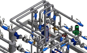
One of the biggest benefits for those who have a detailing department, is the integration with various CAD programs and shop fabrication equipment.

construction estimating software cad bim integrationThis allows you to share one database and guarantees consistency from estimating to detailing to fabrication.

This makes for a huge labor savings because when the detailing department finishes laying out the project, the CAD software program can export a file that can be imported into the construction estimating software program which will execute an estimate without any time spent doing a material takeoff.

Ask if this feature is available with the construction estimating software and which CAD/BIM programs its compatible with.

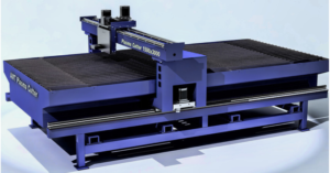
Shop Fabrication Integration

shop integration plasma cutterThere are many construction estimating software programs that now integrate with shop fabrication equipment, especially for sheet metal.

The program shares an integrated database that keeps consistency between the estimating department, detailing and the fabrication shop.

The program would allow the estimating takeoff to be downloaded to the shop equipment for direct fabrication. In most cases you would want this to come from your detailing department to make sure what you fabricate will actually fit in the space allocated on site. Ask your software vendor what fabrication equipment if any the program is compatible with.

Construction Assemblies

estimating construction assembliesOne of the great benefits of estimating software is its ability to provide equipment connections of various sizes quickly and with updated pricing. An assembly is all the pipe, valves and fittings around a piece of equipment or fixture.

For example, a Chiller or Pump often requires the same pipe, valves and fittings whenever one is installed, so why repeat taking off the same bill of materials when an assembly in the construction estimating software can retain all those parts for you.

All you do is ask for a chiller connection of a particular size and the software calculates the bill of materials with the latest up to date pricing and includes all the labor for those parts.
Ask your vendor how many pre-built assemblies come with the program.

Estimating Reports and Spreadsheets

The estimating software has the ability to run many different reports, from material and labor summaries to isolation of separate zones or alternates for review. The important thing is that if you have a special way of reviewing material and labor summaries and breakdowns.

estimating reports and spreadsheetsIts important to make sure that the software is capable of giving you reports the way you desire. I have paid various estimating software vendors to make special reports for the way we wanted to see the print outs.

Most of the estimating software programs also come with a spreadsheet for the summation of the information coming from the database from within the software, and for which you will add additional pricing to comprise a total bid.

To the spreadsheet you will add subcontractor pricing, equipment and specialty items not included in your estimating software. The estimating software might also export data that you would then import into another program like Excel. Ask about the versatility of the reporting capabilities.

Sheet Metal Construction Standards

Contained in the sheet metal estimating program should be rectangular, round and oval duct with the capability to setup any wildcard duct system, such as fiberglass, stainless, black iron and aluminum.

The construction estimating software Sheet metal construction standards setup in the database may vary from how you fabricate and breakdown duct sizes in the way of seams, joints and reinforcement.

estimating sheet metalPart of your implementation time will be spent setting up these standards according to the way you fabricate ductwork.

The system should at least come setup with static pressure classes from minus two (-2) to positive six (+6) inches of static pressure.

The construction estimating program should also contain the capability to either enter values for shop fabrication or for the purchasing of ductwork. Ask which pressure classes come pre-setup.

HVAC Piping Construction Standards

Construction Estimating software programs contain many different piping material types that can be combined in various size breaks, such as using copper up to 2” and carbon steel from 2-1/2” and up, all setup under one system, such as Chilled Water, Heating Hot Water or Condenser Water.

Estimating pipingThe question to ask is how many systems come pre-setup and which ones? If you use various other types of materials like Polypro or Press-fit type fittings, be sure to ask if they are available in the database.

Often times if they haven’t been setup already this will create extra time to implement the system for the type of materials you commonly use.

Plumbing Construction Standards

The mechanical estimating software will also have many piping materials that can be combined to comprise the required systems for plumbing, such as copper, cast iron, plastics, ABS and others. The same questions apply here as for the HVAC piping construction standards above.

Automatic Fittings, Hangers and Joints Generated

Forget about counting hangers as the software will automatically provide hangers according to the hanger spacing set in the construction standards. All you need to do most often is to indicate what the upper attachment will be fasten to, such as concrete, wood or steel beams.

estimating software automatic fittings and hangersAnother great feature is the automation of fittings and joints including all the parts that comprise a joint. No more worrying about or having to remember what is required each time you make a fitting or joint connection.

Once your setup, or confirm that the database holds the correct information for the materials you use on your standard fittings and joints, the system will provide a hanger per the hanger schedule in the software, and all the required components surrounding an elbow, tee, joint or connection without you having to tell the system where the fitting is or the parts needed.

This makes for extremely fast take-offs because there is no need to take-off each individual fitting. Ask your mechanical estimating software vendor if this feature is available.

On-Screen Takeoffs

Onscreen capabilities allow you to do takeoffs directly from digital plans on your computer screen, reducing the time and cost of printing and manually marking paper copies. The On-Screen digitizer supports a wide variety of popular CAD formats in addition to the following; PDF, JPEG, TIF, GIF, PNG and many others.

Check with your vendor to make sure the program accepts your file types. The program should allow real time panning, zooming and marking of very large CAD drawings while minimizing the impact on the computers performance. On-screen takeoffs has moved away from the use of digitizers, computerized table tops.

Specification Swapping

Having this feature allows you to switch the specification of your takeoff with another specification type without having to input each item into the system over again. For instance, if you took off everything as being copper, then with this feature you could just swap out the copper construction specifications with any other specification, like black iron, carbon steel, or some form of plastic.

Mobile Apps for Estimating

mobile construction estimatingSome of these mechanical estimating software companies offer mobile applications that are compatible with their main program. This allows you to do a field takeoff and then import a file into the main estimating program back at the office. Ask about this feature and its cost and capabilities.

They may integrate with Apples iPad or an Android, be sure to ask.

Comparing Drawing Changes

When you receive changes or an addendum to the drawings that you have already done a takeoff on, this feature allows the software to compare the two drawings and highlight or indicate the differences. This saves time when addressing addendums and change-orders.

Software Documentation & Videos

This is one area where you may find that some of them are lacking, as it takes considerable effort to put together and keep updated documentation of the functionality of the mechanical estimating software.

Many vendors now have videos online and don’t provide any written documentation. Be sure to ask about the type and amount of documentation available. Having the ability to refer to training videos or documentation is helpful when you want to learn more about the programs capabilities or just for troubleshooting a simple problem before calling technical support.

Accounting Software Integration

Some mechanical construction estimating software programs have the capability to export data to various accounting software programs. This is useful if you want to save time in setting up a project for the construction department for labor and material tracking.

Having the ability to export all the material and labor values from your estimating program broken down by zone, floor or system type is a convenient and fast way to transition a successful project from estimating to operations quickly.

Its important to make sure that your accounting software is on the estimating software’s list of compatible programs. Its possible also that the estimating software can export into Excel or a commonly used format like CSV or a ODBC Compliant file.

Construction Scheduling Software Integration

construction schedule integrationAgain another feature that can be useful if you want to export data into other programs, in this case scheduling software like MS Project.

This is another time saving feature that is beneficial for those that provide construction project schedules in the various scheduling programs available.

Network or Standalone Based License

Licensing comes in various forms for the different methods of your company’s IT setup and estimating accessibility requirements.
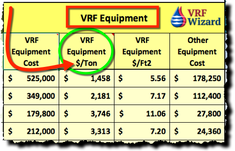
estimating software networkIf there is just one estimator, then the question comes down to whether you want the program to reside on a network server or the Cloud which is accessible from many locations or if the program will reside on your laptop or desktop and be accessible to just yourself (Stand alone).

Often with a Network based installation it doesn’t cost anymore if you have one or ten estimators connected to the network software license, because the cost is for the quantity of licenses, not the quantity of estimators.

If you have four estimators and only one license, then only one estimator can use the software at a time, and you only pay for one license. You have to evaluate how often the estimating software will be used and for which trades.

Technical Requirements

Be sure to verify that your current computer has the required specifications to handle the requirements of the construction estimating software program.

Construction estimating software computer technical requirementsWith the increased functionality and graphics used with some of these programs you want to make sure that your computer can keep up, especially if you are using a network license with many users in different locations.

If using a network and you have users in different cities or locations all using the same server to retrieve the Estimating Program, be sure you have the band width to handle the data transfer required. Make sure to ask all the pertinent questions before purchasing any construction estimating software.

Implementation of the Software Program

It takes considerable effort to get the program setup to match your company’s way of doing business.

Most programs come setup with the basic construction standards, but if yours differ you’ll need to spend time implementing changes to match your company’s’ way of building projects. Whether you do sheet metal, HVAC piping or plumbing, there are construction standards that come prepackaged with most software programs.

Often SMACNA standards or something similar for sheet metal fabrication will come preset and will need to be adjusted for any local code variances in joints, seams, gages or reinforcement.

HVAC piping and plumbing will have copper, cast iron no-hub, plastic, carbon steel and refrigeration piping already setup, but once again you have to confirm that it is the same as your company’s construction standards and the local code authority.
Make sure to allow time for implementation.

My experience is that most construction estimating software vendors understate the amount of time it takes to implement their programs, so I would expect anywhere from 2 to 8 weeks depending on how many systems you need and how close your company standards are to the boxed standards that come with the mechanical estimating software program.

Estimator Experience

Do you or your estimator have any experience using construction estimating software? Training will be required in the range of 3 to 5 days. Beyond this you will need to invest time implementing and learning the nuances of the program to become efficient at take-offs including time to maintain the database.

Anyone that has the basic understanding of computers will learn quickly how to do takeoffs. Someone who understands construction standards will be required as administrator for implementation and for communicating with the technical support staff.

Estimating Software Demonstration

We recommend that you get a FREE demonstration of the various software programs so you can evaluate your needs against the available features and cost of the different construction estimating software programs.

For a FREE demonstration visit one of the following Mechanical Estimating Software providers below or search online for others. They are listed in no particular order. Make sure that you get several demos from different vendors.

TrimbleTrimble mechanical estimating software Mechanical Estimating Software


FastEstfastest mechanical estimating software Mechanical Estimating Software


Wendeswendes mechanical estimating software Mechanical Estimating Software


QuoteSoftquotesoft mechanical estimating software Mechanical Estimating Software

MEP Academy Online Courses
HVAC Sheet Metal Courses Online

VRF Rooftop Fan Coils

0
VRF Rooftop Fan Coils

Rooftop VRF Fan Coils

The latest in VRF innovation is coming this summer with the introduction of Carriers Rooftop VRF Fan Coils that will replace existing HVAC Rooftop Packaged Units. Instead of replacing the HVAC rooftop packaged unit with another newer model, you’ll now have the option of using that same roof curb to install a new Carrier Rooftop VRF Fan Coil.

VRF Replaces Rooftop Packaged Unit

For 3, 4 and 5 ton rooftop packaged units, whether vertical or horizontal discharge there will be an opportunity to switch existing rooftop units out with Carrier’s VRF Rooftop Fan Coils. The Carrier VRF Rooftop Fan Coils will not have a compressor or condenser coil & fan, so it will be much lighter. For those of you living under a strict seismic code or an upgraded structural code which made changing out an old packaged a structural upgrade nightmare, this will ease your pain.

VRF Unit Replace HVAC Package Unit
Pour a Concrete Pad and set new VRF Outdoor Units

There is no need for adapter curbs as the new Toshiba Carrier VRF Rooftop unit sits on the same curb that the old Carrier Packaged DX units sat on. If the manufacture of the existing unit is different then the new Toshiba Carrier VRF Rooftop Fan Coils manufacture then an adapter curb would be required.

DSA & Structural Upgrades

One of the key benefits for contractors in California is that the Toshiba Carrier VRF Rooftop unit will be much lighter, helping you avoid any DSA (Department of State Architect) issues. The DSA reviews plans for public school construction and certain other state funded building projects to ensure that plans, specifications, and construction comply with California’s building codes (Title 24 of the California Code of Regulations).

To get around that review when replacing existing HVAC rooftop packaged units is to remain within a small percentage of the original unit’s weight. The concern when replacing like for like, packaged rooftop units is that the new units will weigh more and trigger a DSA review or structural upgrades due to the increase in the structural code since the units were first installed.

For those of you in other states or countries this factor may not apply, unless you have similar requirements. The new Toshiba Carrier VRF Rooftop Fan Coils weight much less than the existing HVAC Rooftop unit because it doesn’t contain the compressor, condenser or condenser fan.
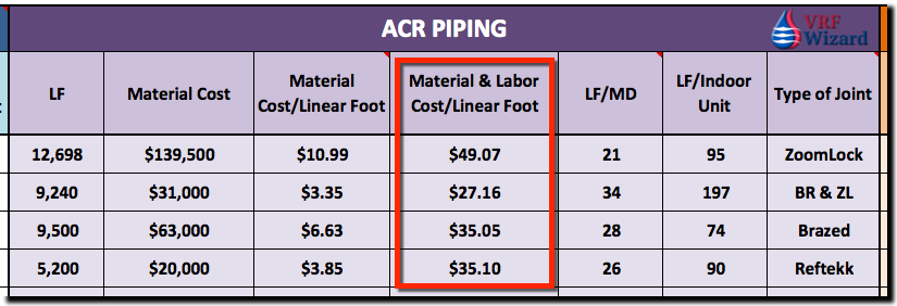
If you have a building that has several 3 to 5-Ton rooftop packaged units, then you can use this new Toshiba Carrier VRF Rooftop unit to replace those Packaged DX units easily with a new VRF system. The Carrier VRF system is a 3-pipe system for VRF Heat Recovery and two-pipe for a heat pump system. The minimum outdoor tonnage is six tons.

VRF Components Housed in Rooftop Unit

All the components for the VRF system can be housed in the same box that the rooftop packaged unit manufacture is already using. The manufacture can just repurpose the packaged unit housing for the VRF components, which will leave plenty of room, as there is no need to house the compressor, condenser coil or condenser fan. When using a VRF Heat Recovery system the Branch Selector Box will be located within rooftop unit housing in some of that vacated space. The branch selector box will be a single port box dedicated to that unit.

Of course you will need to add new VRF outdoor units, refrigerant piping, electrical and some controls.

ASHRAE 15 & 34

One of the key benefits is that ASHRAE 15 & 34 to become a non-issue as there is no need to run the refrigerant piping within the space, unless you want to pick up some indoor fan coils.

Ventilation Air

The ASHRAE requirement to provide fresh outside air becomes a lot easier with this innovative VRF system as the Fan Coil portion of the system is outside where outside air is easily accessed. There is no need for a DOAS (dedicated outside air system) to feed these units, unless of course you have VRF fan coils that you would like to put on the inside of the building. Having the VRF fan coil replace old rooftop packaged DX systems eliminates the engineering challenge of providing a duct to each space or fan coil on the inside of the building.

VRF Manufactures Race to Compete in this new Market

Carrier has released their new innovative VRF Rooftop Unit which I’m sure will be followed by their competitions versions. As the market develops an appetite for these units the competitors will seek to join in on this innovation and grab a portion of the market for themselves. Start to identify opportunities for this new solution so that you are ahead of the competition.

Steps for Replacing Rooftop Package Units with VRF System

The following is brief outline of the steps you might take to replace the Rooftop Package Units. It does’t matter if the existing units were manufactured by units Trane, Lennox, Carrier, Day & Night, Daikin, etc.. The only difference in the beginning when the first manufacture enters the game the summer of 2018 is if that manufacture is replacing its own unit which would avoid the use of an adapter curb.

Step 1 – Design

Engineering review and design. Determine if the project makes financial sense for the owner, if so, secure engineering and documentation for jurisdictional approval. If the owner has decided to use the Design/Build method then this will shorten the schedule and make for a more collaborative approach.

Step 2 – Prepare for New VRF System

Before removing the existing HVAC Rooftop Package units, you will need to prepare the VRF system in advance so that there is minimum disruption of the HVAC system and occupants.

  • Pour Concrete Pads for Outdoor VRF Units or Platforms on the Roof.
  • Run new ACR Refrigerant Piping from Outdoor Units to the existing HVAC Packaged Units. Stub ACR Piping for future connection.
  • Run new Electrical to the Outdoor VRF Units.

VRF ACR Piping and HVAC Package Unit
Install Piping & Electrical from new VRF Outdoor Units to Existing Rooftop AC Units

  • Run control wire from Outdoor Units to existing Rooftop AC units for future connection.
  • Install Main Controller if being used.

Step 3 – Remove Existing HVAC Rooftop Units

With most of the new VRF system installed, the last part will be the removal of the existing rooftop packaged HVAC units.

  • Mobilize a crane to remove the existing rooftop HVAC units and install the new VRF Rooftop Fan Coils.

VRF Rooftop Replace HVAC Package Unit
Remove existing HVAC rooftop Units

Step 4 – Install New VRF Rooftop Fan Coils

  • Install the new Carrier VRF Rooftop Fan Coils onto the existing roof curbs or onto new adapter curbs if units are from a different manufacture.
  • Connect ACR Refrigerant piping, control wiring & electrical. Charge with refrigerant, start and test.

VRF Rooftop Fan Coils
Install New VRF Rooftop Units and Connect Piping, Controls & Electrical.

Summary of Advantages

  • Lighter weight
  • Avoids DSA review
  • No structural upgrades
  • Avoid ASHRAE 15 & #34 issues with refrigerant monitor and minimum space requirements.
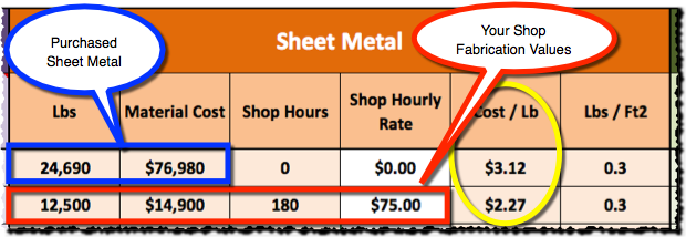
  • No DOAS or installation of outside air ducts. Direct access to OSA.
  • Sits on existing manufactures curb or use an adapter curb with existing manufactures unit
  • Increased efficiency
  • No loud compressor above space below
  • Some of the same options available on VRF Rooftop unit as a new Packaged DX unit. (Controls, Smoke Detector, etc …)
  • Branch selector box installed in VRF Rooftop unit.
  • Static pressures of 3/4” to 1” on efficient ECM fan motor
  • More cost efficient over traditional VRF installations.

Disadvantages

  • Need a new location for the Outdoor Air Units
  • New electrical for Outdoor Units
  • Installation of new refrigerant piping
  • More expensive then a like for like replacement

Get Toshiba – Carriers Engineering Document for their 40QQ Variable Refrigerant Flow Rooftop System.

HVAC Estimating spreadsheet

Subscribe to our mailing list

* indicates required


ZoomLock Crimping Tool Review

0
ZoomLock crimping tool review

ZoomLock™ Tool Review

For those of you that are new to press-fit tools we will cover the features of the Klauke 19 kn tool used on ZoomLock™ fittings, this includes the tool, jaw sets, fittings and accessories required to make a joint.

Klauke 19 kn Zoomlock Tool

You maybe familiar with ProPress™, which is a similar press-fit fitting that is used in water applications, such as Domestic Plumbing, Heating Hot Water, Chilled Water and Condenser Water. The ZoomLock™ fitting is being used in refrigeration systems, allowing you to avoid using a torch. This is definitely an innovative fitting and tool.

Just like your car this tool has a brake, except unlike your car you don’t need to push any additional pedals or buttons; the tool automatically brakes and stops the forward motion of the piston when you release the trigger button. Similar to the bumper cars at the fair, when you let your foot off the gas the car wants to stop. The Ridgid tool keeps pressing until the cycle is complete, so there is no turning back, at least the Kluake will allow you to stop.

There is no need to hold a flashlight on the area where you’re making the fitting as the tool uses a white LED to illuminate the working space after activating the trigger. The light will automatically go off after 10 seconds from the release of the trigger. This feature is also capable of being deactivated.

You don’t have to worry about whether you squeezed the fitting hard enough as the tool has a built-in pressure sensor that will sound an alarm if the minimum required pressure was not applied. And when the required pressure has been reached the tool automatically retracts to its starting position. In the case that you didn’t achieve the required pressure you can manually return the piston to the starting position.

The head of the tool can rotate 350 degrees allowing you to access difficult to reach fittings in corners and around objects, the Ridgid tool is limited to 270 degrees.

Klauke Zoomlock tool jaw rotation
Klauke Zoomlock Tool Jaw Rotation

For all of you concerned about the environment, not only does this tool avoid the use of burning fuel, but the oil used is biologically biodegradable and nonhazardous to water for which they received the Blue Angel award which is a German environmental label.

Blue Angel eco Label Kluake Tool
Blue Angel Eco Label Kluake Tool

The tool has the capability of providing a printout documenting the proper function of the tool at the end of your project by using a USB adapter.

Make sure you read and follow the installation instruction to avoid the improper use of ZoomLock™ fittings and accessories which could cause death, personal injury or property damage as stated in their brochure. You can also do a lot of damage with a torch if you don’t follow directions.

Also, with any refrigerant containing system you’ll want to comply with ASHRAE-15 & 32 to ensure the safety of the occupants if there was a leak in the system, this applies with either a ZoomLock™ fitting or a brazed fitting.

The ZoomLock™ fitting uses a special HNBR O-Ring within the fitting that provides a tight seal after properly being pressed with the Jaws of an approved tool such as the Klauke 19 kn for sizes from 1/4” up to 1-3/8”.

For high pressure refrigerants like 410A, special jaws are required. You can’t use the same jaws that you use for your ProPress or other low pressure press-fit systems. Also, the positioning of the jaw differs when using a ZoomLock fitting versus a ProPress or other low pressure press-fit fitting. (See image below for positioning)

The ZoomLock™ fitting comes in Copper or Aluminum for the use on their respective refrigeration systems. In this review we are discussing the use of the copper fitting on copper tubing.

 ZoomLock Tool Kit Description

The ZoomLock 5 Jaw Tool Kit comes with the following

  • Padded carrying case made of durable plastic.
  • Inside the case you will find a Tube Cutter, Deburring Tool, Crimp Gauge, Depth Gauge, Stainless Steel Brush, Abrasive Pad and Permanent Marker. (See image below)
  • Jaw sizes include , 3/8”, 1/2”, 5/8”, 7/8” & 1-1/8”. The following jaw sizes are sold separately; 1/4”, 5/16”, 3/4″ & 1-3/8″. You can buy the tool without the jaws, or get either the 5-jaw or 8-jaw set.
  • It comes with two (2) Rechargeable 18-volt Makita batteries with a 15 minute charging time for the 1.3 ah (amp-hour) battery, and 22 minutes to charge a 3.0 ah battery. The higher amp-hour batteries can provide more connections per charge, but add more weight to the tool. With two batteries you’ll never be without crimping power.
  • With the 1.3 ah battery you get 150 cycles per charge and with the 3.0 ah battery you can get 300 cycles per charge.
  • There is a 2 year warranty from the time of the delivery of the tool and 5-years on the fittings.
  • The tool with the battery attached weights 1.88kg or 4.1 lbs as opposed to the Ridgid tool which weights over 6 pounds.
  • The pressing cycle is about 3-4 seconds
  • Thrust force is 19 Kn (Kilo newton) or 4,271 Lbs.
  • You can buy the Tool without the Jaws, or get either a 5-Jaw or 8-Jaw Set.
zoomlock tool case accessories
ZoomLock Tool Case Accessories
  1. Two Batteries
  2. Deburring Tool
  3. Crimp Gauge
  4. Tube Cutter
  5. Depth Gauge
  6. Stainless Steel Brush
  7. Marker
  8. Abrasive Pad

Pros, Cons & Comparison

ZoomLock Tool - Klauke 19 kn Review Infographic

ZoomLock Tool vs Brazed
ZoomLock Tool vs Brazing

The advantages of using a Press-fit fitting with the Klauke kN 19 is that there is

  • No Brazing Necessary
  • No Nitrogen purge required
  • No danger of particulate formation
  • No danger of melting or burning of ambient materials in the area (such as adjacent wiring and pneumatic lines)
  • No burn permits needed
  • No fire brigade standby necessary
  • No shutdown of smoke or fire sensors in the area
  • No cooling of brazed joints – immediate usage following leak test
  • No solder residue clogging or damaging inline devices like expansion valves
  • Minimum customer/patient/tenant disruption
  • Labor savings of 60% or greater
  • Less training and a lower skill level required to make a proper joint
  • Avoids toxic substances created by burning refrigerant and oil residue with torch. See the links at the end of this article for research that documents the toxicity of brazing.
  • Battery only requires 15 minutes to charge. (1.3 Ah)
  • 150 cycles per charge
  • Only 3 to 4 seconds per pressing cycle
  • 350 degree rotating head
  • Light weight and well balanced when operating
  • It has the following agency approvals, UL 207, ASHRAE-15, 2015 IMC, IRC & UMC

The Cons or Disadvantage of the Klauke or the ZoomLock fitting;

  • Educating the customer, engineer or owner on the benefits and features of a press-fit joint
  • Resistance to change can be a challenge at some companies and amongst some leaders. In this situation the best thing to do is get your vendor to demonstrate the tool and fitting to the decision makers.
  • Cost of the fittings, clamps and tool.
  • Remembering to crimp the 1-3/8” fitting twice. This size requires two cycles of crimping.

Other Fittings & Tools

There are other press-fit fittings used for refrigerant piping such as the Lokring fitting and other tool manufactures such as Ridgid. The Lokring composite fitting requires 5 individual pieces to make a joint, so it’s more labor intensive than the one piece ZoomLock™ fitting.

There is also Bendable Copper that saves on fittings and reduces brazing labor up to 70% +, see Reftekk Bendable Copper.

You can also checkout the SmartLock Fitting which saves up to 90% of the labor compared to a brazed fitting according to the manufacture.

Ridgid makes the RP 100-B, RP 200-B, RP 210-B, RP 240 & RP 241 with Jaw sizes from 1/4” to 1-3/8”. The Klauke rotates 350 degrees and is a couple pounds lighter than the Ridgid tool, which makes a big difference when you are holding it above your head or trying to rotate the head in a tight space to make a connection.

Who Should Own This Tool

Having this tool available can save time and money for contractors as time is money and the quicker you can get in and out of a job, the more jobs you can get done in a day.

For maintenance personnel and building owners this product can help them quickly repair a leak without the need for a torch or waiting for a contractor to show up or schedule it into their schedule.

Installation Instructions

Here we will briefly cover the installation requirements when using the Klauke 19 kn and  ZoomLock™ fittings. Remember to achieve a leak free system, it’s imperative to follow the simple protocol as defined by the manufacture. Don’t cut corners or use sub-standard tools.

Step 1 – Cut the copper tubing using an approved pipe cutter. Don’t use a saw or other type of blade that will cause the end of the pipe to have a rough finish or sharp edge, as this could damage the O-Ring and provide a path for a leak to occur. Make sure your tube cutter is sharp and in good working order.

Use a Tube Cutter, not a saw.

Step 2 – Use the deburring tool that comes in the Klauke kit, rotate it 5 to 7 times to remove any outer burrs that could damage the O-Ring. Don’t slide the fitting over a recently cut piece of tubing without first removing any sharp edges or burrs caused by the tube cutter.

Remove all Sharp Edges by Deburring

Step 3 – You must then sand and clean the outer tubing by rotating the heavy duty abrasive pad provided with the kit or by using 180 grit sandpaper. Do this for 5 to 7 seconds or 10 to 14 times back-and-forth to remove residual debris from the tubing ends. Don’t sand lengthwise, but use a rotating motion around the circumference of the tubing.

abrasive pad
Clean the tubing with the Abrasive Pad

Step 4 – Make sure to visually inspect the copper tubing after sanding to make sure that there aren’t any scratches, incisions or other marks that could interfere with the proper sealing of the fitting. Don’t use tubing that has scratches, incisions or other defects within the first 1-1/2” of the tube end. Remove amy defects and repeat the above steps to secure a leak free connection.

Step 5 – With the marker and depth gauge provided you will indicate the depth that the fitting must slip over the tubing in order to provide the needed tubing insertion length. Slide your tubing onto the depth gauge in the slot indicated by the size of your tube. Using the permanent marker, make a mark on the tubing as indicated by the gauge for the proper insertion depth. Don’t estimate or eyeball the depth without the use of the depth gauge or by measuring using the chart.

zoomlock depth gauge
Mark the Tubing with the Depth Gauge

Step 6 – Take your ZoomLock fitting and slide it onto your tubing making sure that the end of the fitting reaches the insertion mark from step 5. Don’t proceed unless the insertion depth has been reached.

marker zoomlock
Make sure that the ZoomLock fitting is inserted to the mark on the tubing

Step 7 – Place the jaws of the Klauke crimping tool over the ZoomLock fitting making sure that the center of the jaw is between the O-Ring and outer flange of the fitting. The outer grooves of the jaw should be both on the O-Ring and the outer flange, with the center of the jaw in between them.  Don’t place the center of the jaw onto the O-Ring as done with a ProPress fitting.

See Video below for Tool Demonstration

Step 8 – Press and hold the trigger of the crimping tool until the crimping cycle is complete.

Step 9 – Remove the jaw from the fitting. If the jaws won’t open then the crimping cycle wasn’t completed. In this case you would need to press the manual override button to release the jaws.

Step 10 – For a fitting sized 1-3/8” you will need to provide a second crimping with the tool positioned 45 to 90 degrees from the first crimp cycle. Don’t forget to provide the second crimping of any fitting 1-3/8” in size.

Step 11 – As part of the QC process and if the fitting was properly crimped you should see the letters “RLS” imprinted in the grooves of the crimped fitting. RLS (Rapid Locking System) is the initials of the company that has a patent on the fittings which was licensed to Parker Sporlan and marketed under the trade name of ZoomLock™. RLS LLC is part of The Marmon Group, a Berkshire Hathaway Company.

  1. When properly crimped you should see the letters RLS imposed on the pressed fitting
  2. This dimple prevents the tubing from being inserted to far from one side and provides a stopping point for each tube.
  3. The O-Ring
  4. Fittings outer Flare.
  5. The Jaw is centered between the Outer Flare (#4) and O-Ring (#6).

Step 12 – The second part of the QC process is again to confirm that the crimp was done successfully. Using the Crimp Gauge provided in the kit, you will confirm that the diameter of the finished crimp band fits snuggly into the crimp gauge based on the size of the fitting used. Don’t proceed any further unless the Crimp Gauge fits snuggly around the crimp.

Conclusion

The Klauke 19 kn is a great tool for those considering using ZoomLock or for those replacing an existing tool. The Klauke 19 kn is light weight, well balanced and provides  a 350 Degree rotating head which we believe will make installation easier when you find yourself in hard to reach places, like most conditions on job sites.

The ZoomLock tool definitely fits into the contractor’s bag of go-to-tools and should be something that you offer as the main option to the torch and flame method. The cost of the ZoomLock™ fittings has to be compared against the labor savings, as the fittings are on average 14 times as costly as a brazed fitting, but the 60% or greater reduction in time to make a joint will save considerably on labor cost depending on your labor rates. In addition the extra cost of the fitting, you need to thing about the increased safety factor of using a press-fit tool that has no flame or toxic fumes.

One drawback of the press-fit fitting and not the tool is that if you do need to make a brazed joint for some reason, you’ll need to keep the minimum distances as recommended by ZoomLock™ to avoid damaging the O-ring. This distance varies from 5” (127mm) for a 1/4” through 1/2” fitting to 13.75” (349.3mm) for 1-3/8” fitting.

Press-fit fittings are here to stay and are growing in market share and acceptance by engineers, contractors and municipalities. The only question now is when will you adopt this method? It’s possible that your competition has convinced the owner that they can install the required refrigerant piping without subjecting the building to a fire hazard or the occupants to the byproducts of a torch.

When the owner proposes the question to you about your familiarity with ZoomLock, and the amount of projects you have completed using the ZoomLock fitting and press-fit tool, what will your answer be? Don’t let your competition be more innovative than you. Don’t wait for the owner or General Contractor to suggest the use of ZoomLock before you offer the option. Remain an innovator who provides various solutions, instead of a company with only one tool in their toolbox.

It’s not a question about the integrity of the fitting, but about your ability to follow the required procedures to make the proper joint by following the simple installation protocol, and your company’s ability to have a QC policy in place to make sure that protocol is followed and checked regularly. The ZoomLock™ fitting works and has been tested and approved for the refrigerants listed, including the commonly used R410A in VRF systems.

The question is, are you an innovator with more than one tool in your tool box, or will the owner be given that option from your competition?

If you’re not currently using the Klauke tool and the ZoomLock™ fitting, I suggest you call your local representative and get a demonstration and any question you have answered. Make sure that those who are going to use the tool and the decision makers are at the demonstration. Also, checkout the ASHRAE study on Mechanical Piping Joints.
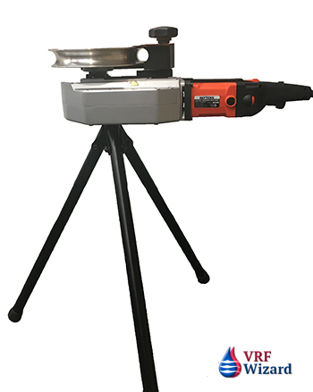
 

References (from Info-graph)

  1. University of Alabama – Environmental Health & Safety – Welding, Cutting & Brazing are Hazardous Activities.

1. Fumes Produced During Brazing.

ZoomLock™ Documentation

  1. Sell Sheet http://www.rlspressfittings.com/wp-content/uploads/2015/12/RLS-sell-sheet-12_15.pdf
  2. Document on 3rd Party Testing. http://www.rlspressfittings.com/wp-content/uploads/2015/01/RLS_Third_Party_Testing.pdf

Disclosures

  1. The VRF Wizard wasn’t paid for this review.
  2. The tool was provided by RLS for this review.

See these other Piping Connections;

  1. Reftekk Piping Connections
  2. LokRing Fittings
  3. SmartLock Fitting
  4. Reftekk Bendable Copper
Important Notice to ZoomLock Users
MEP Academy Online Courses
HVAC Sheet Metal Courses Online

Refrigerant Recovery Machines

0
refrigerant recovery machine

Active vs Passive Refrigerant Recovery

The active removal of refrigerant from a system using Refrigerant Recovery Machines makes the process much easier than using passive methods. The removal of refrigerant from a system that is being repaired or replaced is mandated by the Montreal Protocol which was enacted September 16, 1987 to regulate the production and use of chemicals that contribute to the depletion of Earth’s ozone layer.

Passive Refrigerant Recovery Methods

There are various techniques for removing refrigerant from a system without the use of a refrigerant recovery machine, but note that you won’t get all of the refrigerant out of the system. You can use the compressor to assist the removal or use the migration method.

By running the compressor and attaching your hoses to a service valve on the discharge side of the compressor to retrieve high-pressure gas or to the high-side liquid line, you can get a high percentage of the refrigerant in the system, just not all of it. You will need to cutout the compressor as it nears “0” PSIG on the gauge, at which point you would jeopardize the compressor.

Active Refrigerant Recovery

Refrigerant recovery machines are rated by the speed they remove refrigerant from the system based on three methods, “Push-Pull”, “Liquid” and “Vapor”. The most commonly commercially used refrigerant recovery machine comes with two cylinders for faster removal.

Refrigerant Recovery MachinesRecycling Refrigerant

Recycling differs from recovery in that recycling is a process to reduce the contaminants in refrigerants. This involves the use of filter driers to remove moisture, particulate matter and by separating out oils and removing non-condensable gases.
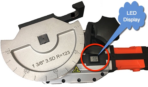
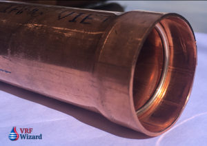
Reclaiming Refrigerant

This process also differs from refrigerant recovery in that reclaiming is the process of cleaning the refrigerant for reuse. This requires that the refrigerant meet a certain specification which can be verified by chemical analysis.
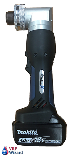
Checkout our review of the different manufactures of Refrigerant Recovery Machines.

Sign up for our newsletter to be notified when other articles are released.


Subscribe to our mailing list

* indicates required