


The compressor is the heart of the system and is located within the Outdoor Unit which can be an air or water-cooled VRF system. The Outdoor Unit will serve multiple indoor units with each VRF manufacture limiting the quantity of indoor units connected to any combination of Outdoor Units. The VRF system varies the flow of refrigerant to each of the connected indoor units based on the needs of that unit, allowing the system to adjust the volume (flow) based on demand.
Each indoor unit uses an expansion valve to control its refrigerant supply to match the cooling / heating demand of the space it serves. The outdoor unit also varies its output to match the total demand of the indoor units. – Danfoss
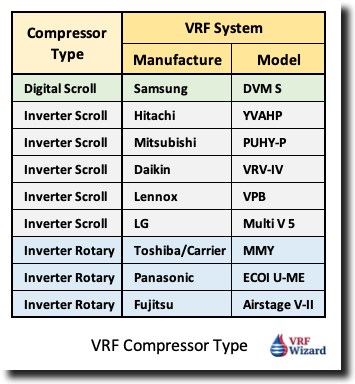
The compressors come in various quantities and types based on the VRF Manufacture and system tonnage. The most used VRF compressor types are the Rotary and Scroll Compressors.
VRF Rotary Compressors
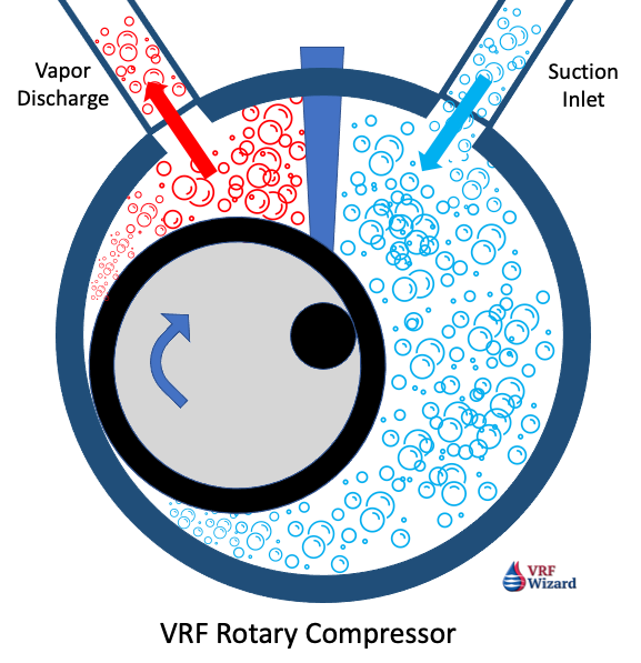
The heart of the rotary compressor is the cylinder which houses the piston and the vane. The vane maintains constant contact with the piston as the piston rolls along the inside wall of the cylinder. As the piston rotates, gas is compressed into an increasingly smaller area until the discharge pressure is reached, releasing gas into the shell chamber. At the same time, more gas comes in through the suction port, enabling a continuous process of suction and discharge.
The simple design and symmetry of the cylinder components, combined with a special coating and premium materials, provide a highly durable and reliable product, rotation after rotation. – Panasonic3
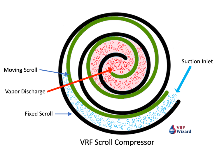
VRF Scroll Compressor
The first scroll compressor for Air Conditioning was produced in 1983 by Hitachi, so scroll compressors have been in development for a long time. These first scroll compressors were most likely constant speed. Copeland states in their literature that they have been developing the scroll compressor since 1979.1
There are two basic types of scroll compressors in use, the ‘Digital Scroll” and the “Inverter Scroll.”
VRF Inverter Scroll Compressor
The Danfoss inverter compressor solution for commercial HVAC applications allows a VRF system to modulate the cooling capacity precisely between 25% and 100% when a single compressor is used, and between 12.5% and 100% with tandem compressors (Modulation range for VZH compressors). The unit adjusts to the varying loads that the building needs during the day. 2
VRF Digital Scroll Compressor
The Copeland Scroll Digital compressor is capable of modulating its capacity from 10% to 100%. The compressor is supplied along with an external solenoid valve. This “normally closed” (deenergized) solenoid valve is a key component for achieving modulation. When the solenoid valve is in its normally closed position, the compressor operates at full capacity. When the solenoid valve is energized, the two scroll elements move apart axially.
During the unloaded state, the compressor motor continues running, but since the scrolls are separated, there is no compression. During the “loaded state”, the compressor delivers 100% capacity and during the “unloaded state”, the compressor delivers 0% capacity. A cycle consists of a “loaded state” and an “unloaded state”. By varying the time of “loaded state” and “unloaded state”, an average capacity is obtained. For instance, in a 20-second cycle, the average capacity is 75%, if the “loaded time” is 15 seconds and the “unloaded time” is 5 seconds. – (Copeland Scroll Digital, page 6, C6.2.15/0815/E)
By controlling the capacity with a solenoid valve the VRF Compressor motor avoids the unnecessary wear caused by frequent start and stop cycles. This method is 30% more efficient then Hot Gas Bypass or Suction Throttling.
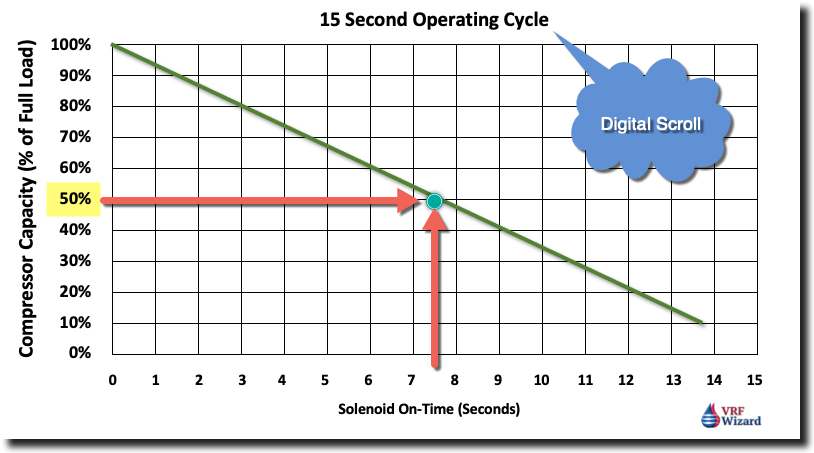
As the chart shows above, the longer the Solenoid Valve is on the less capacity the VRF compressor delivers. If the solenoid is open for 7.5 seconds, which equates to half the cycle time (15 sec.), then the compressor capacity is 50% (half).
VRF Compressor Configurations
You will find a minimum of three versions of VRF System compressor configurations.
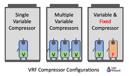
Single Variable Speed Compressor
The compressor will ramp up and down depending on the demand of the indoor units, but won’t have any backup if there is a compressor failure.
Multiple Variable Speed Compressors
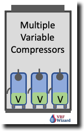
These VRF Outdoor Units can contain two or more compressors and provide redundancy if one of the compressors fail. The VRF controller with sequence the compressor for optimum energy efficiency and shared runtime.
Mixed Compressors – Variable & Fixed Speed
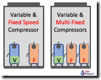
Various VRF Manufactures use a mixture of variable and fixed speed compressors in their outdoor units to handle the indoor unit demand. VRF manufactures may have two or more fixed speed compressors with one variable speed compressor.
VRF Compressor Duty Cycling
When the VRF system contains more than one compressor or connected outdoor unit, the system has the capabilities of optimizing the run-time of each compressor. This ensures that all the compressors share in the hours of operations instead of using the same compressor each time the unit comes on. This should extend the life of the of the VRF compressors by sharing in the total run hours.
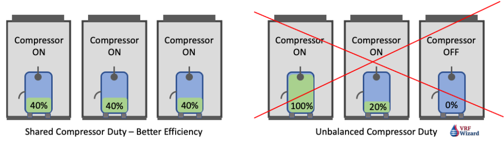
Some VRF system compressors will rotate operation between outdoor units to ensure system efficiency and shared duty. This means some outdoor units will be off while others are running, then during the next duty cycle the unit that was off may now be running while the previous unit that was running is off. Various versions of these scenarios are used by the VRF Manufactures to provide optimum efficiency, compressor longevity and proper sharing of the runtime for each compressor.
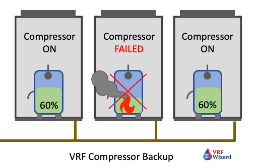
VRF Compressor Backup Operation
Under the same conditions above where you have multiple Compressors or outdoor units, the VRF system can provide partial capacity in the event that one of the compressors or outdoor unit’s malfunction.
VRF Outdoor Unit Capacity
The capacity of the VRF System is rated per AHRI 1230 to establish it’s ‘Integrated Energy Efficiency Ratio (IEER)’ which looks at the summation of four values of various running capacities: 100%, 75%, 50% and 25%, which is one full load condition and three-part load conditions.
IEER – Integrated Energy Efficiency Ratio Formula
IEER = (2% x A) + (61.7% x B) + (23.8% x C) + (12.5% x D)
A = EER at 100% AHRI Standard Conditions (95 F)
B = EER at 75% (81.5 F)
C = EER at 50% (68 F)
D = EER at 25% (65 F)
Efficiencies are higher and energy consumption is lower when running at reduced capacities, so this will be optimized across multiple connected compressors by running them at part loads, before running one compressor at full load. As the IEER formula gives the greatest weight to running at 75% load, followed by 23.8% at 50% load.
Larger capacity systems are achieved by mating several smaller units together.
The use of inverter duty compressors and electronic expansions valves EEV’s provides a method for stable temperatures and pressures in addition to energy savings.
The speed of the compressor will vary based on the cooling or heating demand from each indoor unit which has an expansion valve regulating the flow of liquid refrigerant for cooling or hot gas vapor for heating.
The pertinent information from the positions of the EEV’s and the indoor sensors is communicated to the outdoor unit which makes an adjustment to the volume of refrigerant flowing in the system and the speed of the outdoor fan required to meet the existing conditions, for digital scrolls this would affect the loading or unloading cycle time.
With the Daikin VRV IV system you can choose the temperature response speed, as the outdoor temperature increases so does the evaporative temperature. The response can be very fast (Powerful mode – least efficient), fast (Quick mode) and Medium (Mild Mode – Most energy efficient).
VRF Compressor Manufactures
The compressors contained within the Various VRF Manufactures equipment is often manufactured by another company, one that specializes in compressors like Danfoss or Copeland.
Danfoss is a manufacture of compressors used in various VRF Systems, and according to their statement:
“The Danfoss inverter compressor solution for commercial HVAC applications allows a VRF system to modulate the cooling capacity precisely between 25% and 100% when a single compressor is used, and between 12.5% and 100% with tandem compressors (Modulation range for VZH compressors). The unit adjusts to the varying loads that the building needs during the day.” – Danfoss
Summary
The use of VRF systems and the various compressor types will save on energy and provide the following benefits:
- Precise Cooling & Humidity Management
- Low Startup Current (Soft Start)
- Energy Efficient
- Lower Noise Levels
- Variable Speed
There are other characteristic of a VRF System that contributes to its ability to reduce energy consumption besides its variable refrigerant flow or its variable speed and capacity-modulated inverter duty compressors, this includes the use of multiple compressors or multiple outdoor units. The use of ECM’s motors on the indoor fans and or Variable Speed Drives on Outdoor Unit Fans will also vary based on the cooling or heating load.
References
- Copeland Digital Scroll, https://climate.emerson.com/documents/copeland-digital-scroll-compressors-for-air-conditioning-zrd42k-to-zrd125k-zpd34k-to-zpd182k-application-guidelines-en-gb-4212626.pdf(Accessed 10-25-21)
- Danfoss Inverter Scroll, https://www.danfoss.com/en/markets/refrigeration-and-air-conditioning/dcs/variable-refrigerant-flow/#tab-overview (Accessed 10-25-21)
- Panasonic R2 Inverter Rotary Compressor, https://www.aircon.panasonic.eu/GB_en/happening/new-panasonic-r2-rotary-compressor/ (Accessed 10-25-21)
- Copeland Digital Scroll Compressor Video.
- Hitachi Scroll Compressor Video.
- Danfoss Scroll Compressor Video.


