Home Blog

VRF System Controller

0
VRF Central Controller

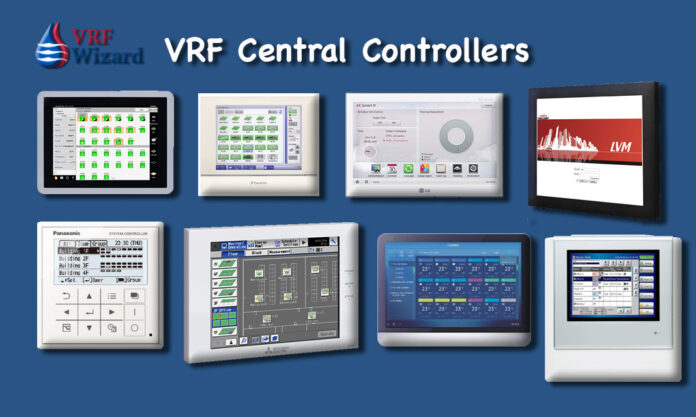
Find comparison on VRF System Central Controllers for all major manufactures. Daikin, Carrier, Toshiba, Panasonic, Mitsubishi, Trane, York, LG, Fujitsu, Lennox,

The following is a look at Touch Screen VRF Central Controllers that are available from the various VRF system manufactures. There are various other control schemes that can be employed to accomplish increased levels of monitoring and control at additional cost. These additional levels of control would include BACnet and similar protocols, in addition to the monitoring of the facilities non-VRF systems, such as lighting, boilers, security and other HVAC equipment. An additional BMS module would be required in most cases in order to connect the Touch Screen Controller to a BMS system.

MEP Academy Online Courses
HVAC Sheet Metal Courses Online

Maximum Indoor Units on Main Controller

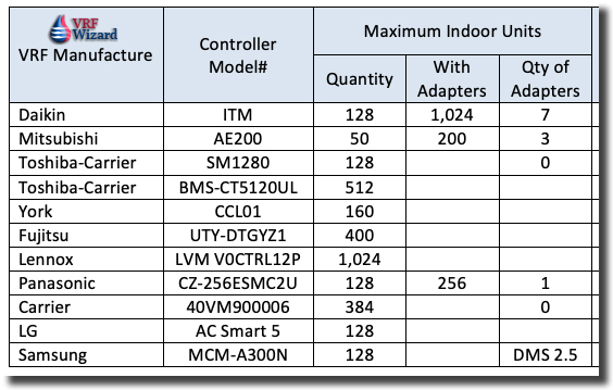
The size of your facility and the quantity of indoor units that you need to monitor from your VRF controller is dictated by the maximum allowable set by each VRF manufacture. Some VRF manufactures have adapters that allow you to expand this maximum even further; other VRF manufactures would require you to purchase another main controller.
VRF Central Controller Comparison
VRF Central Controller – Maximumm Indoor Units

Multiple Indoor units can be operated by one controller and identified as a group within the central controller. Groups allow for easily scheduling or making operational changes to indoor units that belong to the same tenant, zone or other parameter. VRF central controllers will limit the quantity of groups available.  

VRF Controller Display Size

If you’re going to be viewing floor plans on the Display then you will probably want a larger screen size.
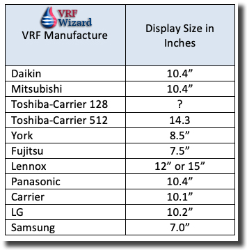
VRF Main Controller Display Size Comparison

Prohibit Remote Controllers

This feature allows the prohibiting of certain functions or adjustments at the tenant level using the remote controller. Certain control settings can be prohibited from being adjusted such as temperature settings, fan speed, on/off, scheduling and others.

You can setup restricted adjustments and then disable/enable the restricted group of settings by changing the accessibility at the central controller. Some Indoor units can be locked out while others are freely adjustable by the tenant. Restrict a portion of the remote controls functionality or all of it. 


Daikin VRV System Controller
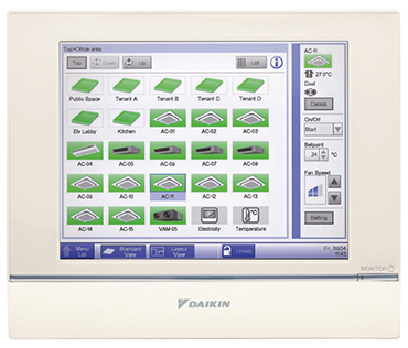
Daikin VRV system Controller
Daikin VRV System Controller

The Daikin VRV Touch Screen Central Controller (ITM Intelligent Touch Manager) comes with the following features:

  • Choice of 3 different screen savers.
  • Area and Group configuration
  • Area contains one (1) or more Area(s) or Group(s)
  • A Group may be an indoor unit, Di, Dio point that has a DIII-NET address
  • The Controller displays On/Off, Operation Mode, Setpoint, Space Temperature, Louver Position, Fan Speed for each Area or Group.
  • Displays date and day of the week along with the time of day
  • Adjust for daylight savings time (DST) automatically.
  • System status icons displays On/Off (color coded), Malfunction/Error (color coded), Forced Stop, Setback, Filter, Maintenance, and Screen Lock.
  • Display of temperature setpoint and room temperature information configurable for Fahrenheit or Celsius
  • Error status displayed in the event of system abnormality/error with one of three color coded icons placed over the indoor unit icon or lower task bar.
  • Error history stores up to 500,000 errors/abnormality events
  • Floor plan layout
  • Capable of displaying site floor plan as the background for visual navigation. Indoor unit, DIII-Net Di and Dio, and External Di, DO, and Ai icons with operational status can be placed on the floor layout
  • Up to 60 floor layout sections can be created
  • BACnet Client Option

Daikin VRV System Controller Submittal

Daikin Website: Daikin VRV System Controller


Mitsubishi VRF Controller AE-200A
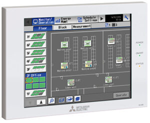
Mitsubishi VRF System Controller AE-200A

The Mitsubishi VRF Touch Screen Central Controller model #AE-200A comes with the following features:

  • Master controller operates 50 Indoor units with expansion controllers to increase to 200 Indoor units
  • Permits or prohibits remote controller functions. Emergency stops with optional component (PAC-YG10HA)
  • Pulse signal input can obtain watt-hour meter, billing data and emergency management data
  • Monitor and control indoor units, Lossnay, PWFY heat pumps, DIDO controllers, DOAS
  • Scheduling
  • Trend data
  • Memory backup via USB or LAN

Mitsubishi VRF System Controller AE-200A Submittal

Link to Website: Mitsubishi VRF Controller

Toshiba – Carrier VRF Controller SM1280
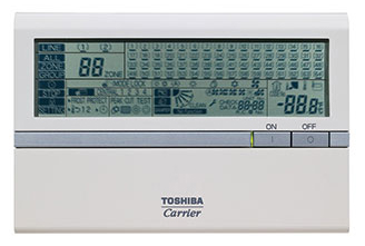
Toshiba Carrier VRF Central Controller Model # BMS-SM1280

The Toshiba-Carrier VRF Touch Screen Central Controller model #BMS-SM1280 comes with the following features:

  • Maximum of 128 indoor units
  • Optional Energy meter (watt-hour)(requires PDI module)
  • Distance from SMART 5 Controller to farthest device shall not exceed 1,000m (3,280’)

Adding I/O modules reduces the amount of devices or indoor units that can be attached to the central controller. 


Toshiba – Carrier VRF Controller CT5120
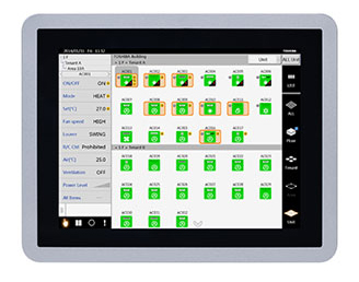
Toshiba Carrier Touch Screen Central VRF Controller BMS-CT5120UL

The Toshiba-Carrier VRF Touch Screen Central Controller model #BMS-CT5120 comes with the following features:

  • Grouping based on floor, unit, area, tenant and level
  • Operating Mode, Turning ON/OFF
  • Enable or disable local remote control
  • Master scheduler: weekly, 5 special days, monthly
  • Display alarm + provide history for alarms
  • Web browser monitoring and control (for intranet PC)
  • Up to 2 concurrent users can be connected
  • Additional digital I/O device available
  • Maximum of 512 indoor units per Touch Screen Controller
  • LCD Color display
  • Compact Flash Card
  • Two RS-485
  • DVD-R manual and Software
  • 120VAC, 60 Hz (12V DC power adapter supplied)
  • USB port for service
  • Optional Energy Monitoring interface module 
  • Optional Digital I/O interface module

Toshiba Carrier VRF Controller Owners Manual

Link to Website: Toshiba Carrier VRF Controller


Tenant Metering

The ability to track the electricity usage by each tenant provides for a convenient means of billing. Each tenant in a building may have hours of usage that differs from their neighbor. With tenant metering you can fairly charge each tenant according to the amount of electricity or for the time their air conditioners are running. 

Scheduling

VRF Central Controllers allow for the operational scheduling of the various zones programmed into the system. It’s imperative that you set up your zones according to usage, separating out rooms that run 24 hours a day or run on the weekend. This will allow certain zones to function after hours while the rest will shutoff to ensure energy efficient operation of the facility. A good way to waste money is to have your HVAC system running when the space is unoccupied. 

Each VRF central controller will allow a limited amount of schedules that can be programmed into the system. Schedules can be given a name that corresponds to particular events or daily fluctuations in operating hours.

The quantity of events that are capable of being set for each schedule created is limited by the program. Setting events lets you control what happens at what time according to your programmed schedule. Each VRF manufactures central controller allows you to manipulate various set points and conditions based on your schedule, such as fan speed, setpoint shift, Temp setback points, pre-cool/pre-heat settings, Prohibit Changes, timer extensions, etc …

Features to look for:

  • Administrative Control
    • Graphical representation of schedule
    • Ability to exclude dates, such as holidays or weekends.
    • Quantity of schedules for a week
    • Quantity of events per schedule setting 
    • Program the schedule by Area/Group/Zone
    • Automatic Schedule switchover based on Season

Mitsubishi VRF Central Controller Schedule: https://youtu.be/tGf-AljutLU


York VRF Controller
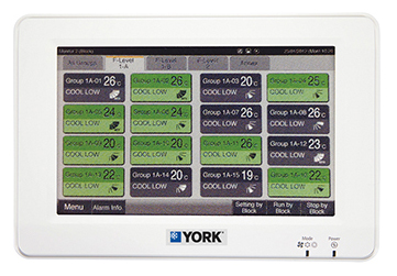
York VRF System Controller

The York VRF Touch Screen Central Controller model #CCL01 comes with the following features:

  • Controls up to 32 groups of indoor units (maximum 160 units).
  • Independent cooling and heating setpoints.
  • Individual zone control with weekly programmable scheduling.
  • Basic central point on/off control of all units.
  • Advanced multi-zone control of small to medium sized projects.
  • Automatic cooling/heating changeover for heat pump systems.
  • Single batch input shutdown of all connected units.
  • Temperature setpoint range restrictions.

Link to Website: York VRF System Controller


Fujitsu VRF System Controller
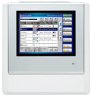
Fujitsu VRF System Controller

The Fujitsu VRF Touch Screen Central Controller model #UTY-DTGYZ1 comes with the following features:

  • Large-sized 7.5-inch TFT color
  • LCD Easy finger touch operation
  • Stylish shape and design to suit all application
  • No additional component is required for installation
  • Up to 400 indoor units can be controlled
  • Optional Electricity Meter
  • Selectable 2 display types (Icon / List) in monitoring mode Air conditioner can be monitored and controlled via LAN from PC.
  • Error contents are notified automatically by E-mail at error occurrence to handle the trouble promptly.

Fujitsu Website: Fujitsu VRF System Controller


MEP Academy Online Courses
HVAC Sheet Metal Courses Online

Lennox VRF System Controller

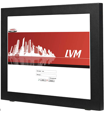
Lennox VRF Touch Panel Central Controller LVM V0CTRL12P
Lennox VRF Touch Panel Central Controller (LVM V0CTRL12P)

The Lennox VRF Touch Panel Central Controller (LVM V0CTRL12P) comes with the following features:

  • Display available in 12” or 15” (LVM V0CTRL15P)
  • Remote access via mobile and desktop devices
  • Scheduling
  • System Monitoring
  • Status history
  • Controls up to 1,024 indoor units
  • Controls up to 64 VRF systems
  • Controls up to 192 Outdoor units
  • Requires Router Switch & Additional LVM Hardware (V0CTRL85)

Lennox Website: Lennox VRF System Controller


Panasonic VRF Central Controller
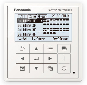
Panasonic VRF Central Controller

The Panasonic VRF Touch Screen Central Controller model #CZ-256ESMC2U comes with the following features:

  • Controls 128 Indoor units and up to 256 with added communication adapter
  • AC24 V, 60 Hz
  • Diagnostic History of System Past and Present
  • Provides Individual Tenant Billing data for 3 systems, additional systems are done by adding Communication Adapters. Requires watt hour meters
  • Individual Zone Override Feature (High/Low Settings)

The Panasonic VRF Central Controller can control unto 64 Indoor Units

Website: Panasonic VRF Central Controller


Carrier VRF Central Controller
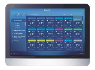
Carrier VRF Touch Screen Central Controller model #40VM900006

The Carrier VRF Touch Screen Central Controller model #40VM900006 provides the following features;

  • Ability to view floor plans
  • Automatically detect connected indoor units
  • Scheduling
  • 1 Administrative & 384 user accounts
  • Alarm notification via email
  • Adjust fan speed, temp range
  • Error display
  • Clock

Carrier VRF Central Controller Website

Carrier VRF Central Controller Installation & Operations Manual


LG VRF System Controller
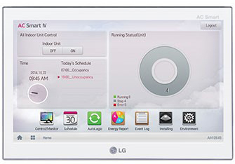
LG VRF Central Controller

The LG Smart 5 VRF Central Controller comes with a wall mounting plate, manual and a SD Card. The SD card is used for data backup and recovery. The LG Smart 5 features a UX-compatible platform that works with a PC, smartphone or tablet. The LG Smart 5 contains the following:

  • 10.2” LCD Touch Screen (C-Type Touch Panel)
  • Dual Core CPU
  • 2 GB of Memory
  • 16 GB of storage
  • Mono speakers
  • 2-Port RS-485
  • SD Card (data backup & recovery)
  • Mini USB (for debugging software), Micro USB (for service)
  • Ethernet 10/100 BASE-T
  • DI (Digital Input) 2 Ports
  • DO (Digital Output) 2 Ports
  • 12V Input Port, 24 V Input Port
  • Integrated BMS system interface

LG VRF System Controller Submittal

LG VRF Controls Catalogue

Website: LG VRF Central Controller


Samsung VRF Central Controller
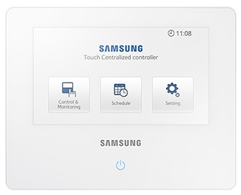
Samsung VRF Touch Screen Central Controller model #MCM-A300N
Samsung VRF Touch Screen Central Controller model #MCM-A300N 

The Samsung VRF Touch Screen Central Controller model #MCM-A300N provides the following features;

  • 7” LCD Touch Screen Controller
  • Maximum of 128 indoor units and Samsung ERV’s
  • Allows creation of zones for indoor unit grouping (12 maximum) with customizable zone icons
  • SD card slot for data backup and future software updates
  • Scheduling (maximum 10 schedules)
  • RS485 communication
  • Control indoor operation of temperature , fan speed, advanced settings, usage, louver control
  • Restrict indoor unit control

Samsung VRF Central Controller Submittal

Samsung VRF Central Controller Design Software link


Operational Settings

VRF Central Controllers vary on their ability to control settings and functions. You can control one component or make global changes to all units using the VRF central controller. A password can be used to lock or allow certain changes to the settings based on what you would like the tenant to be able to change.

Features to look for:

  • Temperature settings
  • Temperature range restrictions (limit High & Low Settings)
  • Fan speed (typical high, medium & low)
  • Louver control (adjust direction of airflow)
  • Mode (Operational control of an attached component)(heating or cooling only)
  • Schedule
  • Controller use restrictions (Permit or Prohibit use of certain settings or functions)
  • On/Off of attached components
  • Language 
  • Passwords (screen can be locked requiring a password)
  • Date and time (12 hour or 24 hour display)
  • Screen display brightness and backlight timeout functionality
  • Ability to move a device from one zone to another
  • Error codes and history of errors
  • Ability to import and display floor plans
  • Error detection notification via email
  • Interlock with non-VRF input devices (Motion sensor, CO2 sensor, Door entry key)
  • Emergency stop
  • Administrators and Users (maximum quantity of admins or users)

Control Wiring

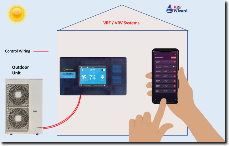
VRF Central Controllers are wired to each component in the system in a daisy chain fashion. This is very efficient method of wiring that allows each component a pathway for the communication wiring to the central controller. If you need to expand the quantity above the allowable limits for the system than you would need to run separate wiring to each of the added adapters that help increase the capacity of the control system.

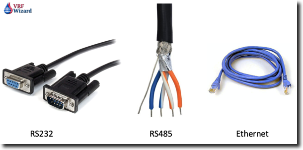
RS485 cabling is the most commonly used connective wiring as it allows for multiple devices to be connected together and allows for longer runs of cabling than the previous RS-232.

The capability to connect to a BACnet system or some other protocol should be available, sometimes as an add-on component. 

Data Backup

There are various methods that the VRF manufactures use to allow data to be backed up and stored in case of power or system failure. Having a backup will save you hours of programming if such a failure occurs and you need to restore your settings. Backup can come in the way of storing the data on a hard drive, thumb drive, the cloud or on some form of Memory card. This may also be the method that the VRF manufacture using to update the system software.

Zone/Area Control

A zone is created by grouping various indoor units together under a common control setting scheme. Combining a group of indoor units that have similar thermal experiences and scheduling requirements will help save on individual programming. You can provide a name for each zone that you create, allowing for quicker recognition of various areas of your facility under control. 

You can group indoor units according to the Outdoor Unit that feeds them in addition to the floor that the indoor unit resides on. See example below.

3rd Floor – ODU-1 – Indoor Unit (Room 345)

Floor Plan Display

A unique feature of the central controller is its ability to import and display floor plans. Having the ability to view the floor plan on the controllers LCD display with the indoor units displayed in the appropriate locations, allows for a quick graphical representation of the overall system layout. The indoor units are represented with icons that are interactive, allowing you to make adjustments to the settings for each unit with a quick touch of the screen. The auto detection feature of the VRF Central Controller will populate the system with individual icons for each indoor unit. 

Mitsubishi Floor Plan Display: https://youtu.be/wa3OzxClvxU

Error Alerts

The VRF Central Controllers allow for email notification when an error occurs in the system. This allows for rapid response to get the error corrected and the system repaired if needed. The email notification allows for various alarms or errors to be directed to different email addresses. If there is an error with the Outdoor Unit, maybe you want two emails sent, one to the building engineer and another to the contractor that services the system. This would allow the contractor to be in route to fix the issue much faster. Error logs can show the history of alarms and what part of the system went into alarm.

Internet/Web Access

Some of the VRF Central Controllers can be viewed over the internet using the appropriate additional hardware in some cases, while others require only an IP address at the site for connection to the controller. Web access allows you to operate and make adjustments to the VRF central controller from a PC or MAC instead of having to be present at the touch screen.

Administrator and Users

The VRF Central Controller usually has two levels of access, one for administrators and another for general users. There is a maximum amount of general users that the system will allow, in addition there is a limit of how many of those users can access the system at the same time.

The administrator can access multiple building sites from an offsite location via the internet. For owners or property management companies that have multiple properties this makes oversight much easier. 

Commissioning

With a VRF system, commissioning is critical to the proper operation of the system. Using a certified trained technician will improve your chances of having the system run as designed. Commissioning will ensure that the initial settings and calibrations are correct and everything is functioning as intended.

Most of the VRF central controls have a self-discovery feature that automatically recognizes any component that is connected properly to the system. This feature will automatically detect any indoor fan coil, outdoor unit or heat recovery box that is wired correctly to the central controller and powered electrically. You will need to run electrical power to energize the VRF central controller. Most VRF central controllers run on 120-240V, 50/60 Hz power

Summary

Having a VRF central controller makes sense if you have a lot of indoor units that you would like to control from a central location or remotely. Having the ability to see what is happening at each indoor unit and having the ability to adjust or lockout the adjustment of any of the settings provides better management of the energy consumption and usage of the air conditioning and heating system. Support this blog by using the following links for any Amazon purchases.

Daikin ITM: https://youtu.be/KD6fDSNMz-E

Additional Daikin ITM Video: https://youtu.be/sD3oYaPsRyA

Samsung: https://youtu.be/4S8Tw_5oTRc

Resources

Daikin VRV Central Controller

York VRF Central Controller

Fujitsu VRF Central Controller
Engineering Videos

0

VRF Compressor Types


VRF Piping Design Software

VRF Piping Design Software

How to Calculate Cooling Coil Heat Transfer


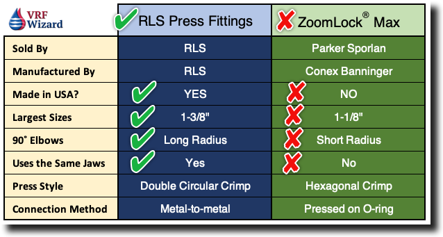
Zoomlock or RLS versus Brazed Piping Joints and Fittings

Zoomlock or RLS versus Brazed Piping Joints and Fittings

How to Calculate COP & KW per Ton

How to Calculate COP & KW per Ton

MEP Academy Online Courses
HVAC Sheet Metal Courses Online

How to Calculate Air Changes per Hour

Calculating Room Air Changes per Hour

VRF Rooftop Packaged Units

VRF Rooftop Packaged Units

ZoomLock Tool Review

ZoomLock Tool review

Energy Meter – Billing Tenants for Energy Use

Energy Meter – Billing Tenants for Energy Use

How to Read a Metric Scale

How to Read a Metric Scale

Calculating Cooling Loads

Calculating Cooling Loads

ZoomLock Value Calculator

ZoomLock Value Calculator

VRF Control Wiring

VRF Control Wiring

Construction Contingency

Construction Contingency

VRF Heat Recovery

VRF Heat Recovery
MEP Academy Online Courses
HVAC Sheet Metal Courses Online

VRF Project Cost Tracker

0
VRF Project Cost Tracking 2

How Much does a VRF System Cost per Ton ($/Ton) or per Square Foot ($/Ft2)? How many Ft2/Ton should you figure? How much does the Electrical Cost per Indoor Unit ($/IDU)? Track all of these and MORE with the VRF Project Cost Tracker Spreadsheet.

Having a method to track the cost, engineering and installation metrics of a VRF/VRV Project will help you understand how to bid or budget these types of projects, along with what the typical project looks like. This VRF Project Cost Tracking Spreadsheet will help you understand the following and more:

  1. How much a VRF System cost per ton
  2. How much a VRF system cost per square foot
  3. How many square feet per ton a typical project in your area has.
  4. How much the VRF Equipment cost per ton.
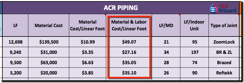
  5. How much your ACR Refrigerant piping cost per linear foot installed.
  6. How many feet of piping can be installed in one man day.
  7. Lots more….

VRF Cost per Ton ($/Ton)

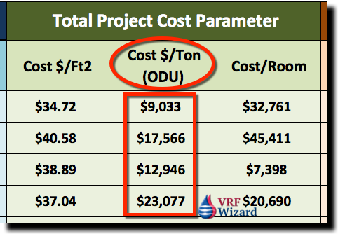
We believe one of the best ways to measure the cost of a VRF or VRV System is to keep track of the Total Cost per Ton for the different types of systems and the various options that effect its variability in cost. If you need to budget a VRF project quickly, there is no better method, followed by cost per square feet.

The VRF Project Cost Tracker Spreadsheet tracks dozens of other useful cost and engineering data.

VRF Project Cost Tracker
VRF Cost per Ton – VRF Project Cost Tracking Spreadsheet

In the above example, the wide spectrum of cost per ton is due to the total scope performed under each of the different VRF projects. Some projects include the cost to provide a turn-key project, meaning you will do all work associated with the installation of the VRF system in addition to the mechanical scope. Under a turn-key retrofit project you may need to pour concrete pads for your outdoor units or build equipment pads on the roof, provide electrical, general construction, etc. This is defined in the scope section of the spreadsheet.

VRF Cost per Ft2 ($/Ft2)

Another useful parametric to track is the cost per square foot to install a VRF system. If you know the square footage of the area that is being provided with a new VRF System, then you can track how much it cost per square foot to furnish and install the system. The below example would have the same cost variables as explained above for additional scope items. These are just examples not actual project values.

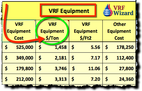
VRF Equipment Cost per Ton ($/Ton)

Another important factor to track is the cost per ton for purchasing just the VRF/VRV Equipment. You will want to use a spreadsheet to track the variables. The VRF Project Cost Tracking spreadsheet should be sortable per those variables for quick reference when doing budgets or checking a current bid or before purchasing VRF equipment.

VRF Equipment Price per Ton
VRF Equipment Price per Ton – VRF Project Cost Tracking Spreadsheet

Using the above project as an example, if your quoted equipment from your vendor for your Heat Recovery System was $150,000, we can then determine what we are paying per ton for this equipment.

  • VRF Equipment Cost $150,000
  • Total ODU (Outdoor Unit) Tonnage = 50 Tons
  • Cost per Ton = $150,000 / 50 Tons = $3,000/Ton

ACR Refrigerant Piping

The total footage required for each project varies based on several factors. One of those factors is the system type. VRF Heat Recovery Systems require more piping than VRF Heat Pump Systems. Then you have 2-pipe versus 3-pipe systems that can affect the total footage on VRF Heat Recovery Systems.

Tracking the total footage will help you understand how the piping affects pricing. We like to look at Linear Foot/Indoor Unit. This will give you a quick reference to how much pipe various projects require and how any project you are currently considering will be affected. (LF/Indoor Unit)

VRF ACR Piping Cost per Linear Feet
VRF ACR Piping Cost per Linear Feet – VRF Project Cost Tracking Spreadsheet

Piping (Linear Foot / Man Day) (LF/MD)

Another factor to consider that impacts cost and which is indicative of the risk of labor, is the productivity factor used for the installation of the ACR piping. The conditions imposed on each project for the installation of the ACR piping is different and is reflected in the overall productivity parametric.

In its basic unit of measurement, piping can be expressed in how many feet of pipe can one man install in a day (Linear Feet per Man Day). This is not to say that the project will only have one piping installer, but is an expression of the overall productivity of the piping crew expressed in its simplest form.

For example, if you had 4 individuals installing a total of 400 feet of ACR Piping and it took them a combined 64 hours, then you could express the total productivity of the 4-person crew in the parametric ‘Linear Feet per Man Day’, with the following calculation;

400 Feet / 64 Hours * 8 Hours/Day = 50 Feet / Day or (50 Feet per Man Day) 50 Ft/MD

Piping – Type of Joint

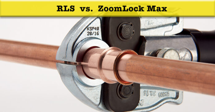
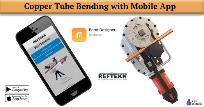
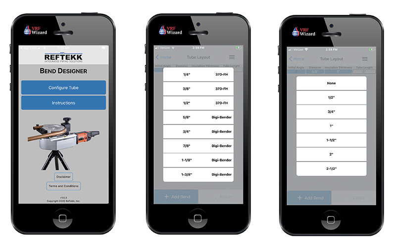
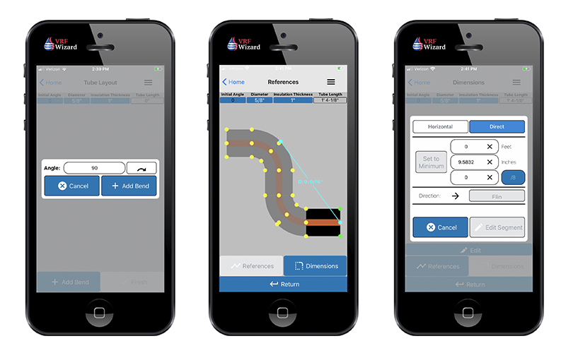
Another factor that you might want to note is the type of joint used that effects productivity. Using a ZoomLock Fitting which avoids brazing can save upwards of 60% of your labor, but your materials will cost more. You could also use Reftekk, which is a piping solution that uses bending soft or bendable copper tubing in lieu of brazing fittings.

This system can save you on labor, but will require the investment of the proper tools including a Swage Expander and Copper Bending Machine, along with the purchasing of the correct type of copper piping. There is another mechanical joint that avoids brazing called LokRing.

HVAC Sheet Metal

How many pounds of sheet metal does one project have compared to another, this will help you adjust for the differences. If your project has mostly wall mounted indoor units, then you won’t have much sheet metal ductwork.

If you’re using a lot of the concealed ducted indoor units or have a ducted outside air system then your project will show a cost impact for sheet metal.

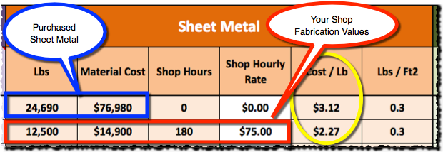
If your company has a sheet metal fabrication shop, then you can put the cost of material and shop hours, if not, then you can just put the cost to purchase the material. Either way you should get the total pounds of sheet metal to help you budget future projects. Knowing the sheet metal cost per pound whether you fabricate or purchase it, will help you understand your cost and use it for budgeting.

VRF Sheet Metal Cost
VRF Sheet Metal Cost – VRF Project Cost Tracking Spreadsheet

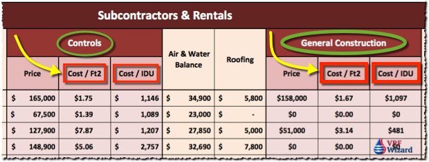
VRF Controls ($/Ft2)

All VRF/VRV Systems have some form of controls. Most of the VRF equipment is daisy-chained together with 16 or 18ga communication wire, while the main controllers require line voltage.

This section of the spreadsheet tracks the cost per square foot and cost per IDU (Indoor Unit) for the controls.

VRF Subcontractors and Rentals
VRF Subcontractors and Rentals – VRF Project Cost Tracking Spreadsheet

In addition to the VRF manufactures required wiring, the owner may have a requirement for BACnet capabilities or the ability to be controlled or viewed from their existing Building Automation system.

Total VRF Project Cost & Engineering Parameters

VRF Engineering Parameters
VRF Engineering Parameters – VRF Project Cost Tracking Spreadsheet

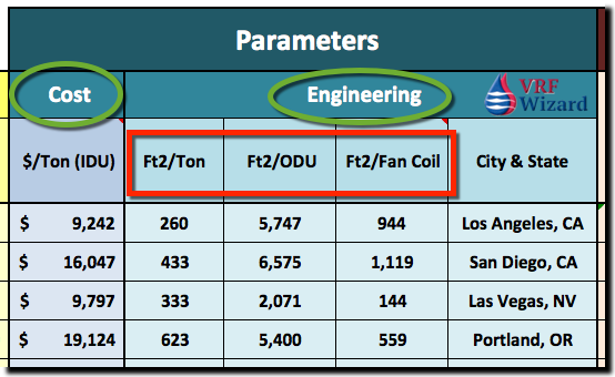
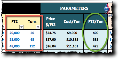
Ft2/Ton

Since you have been recording all the projects that you bid or are involved in, you have information on how many tons a certain type of building has per square feet. If the owner tells you he has a school in Los Angeles, California, then you can filter your spreadsheet for schools and determine from past projects approximately how many square foot per ton is required.

This isn’t scientific, but with experience and some handy data you can make an educated decision on the best Ft2/Ton value to use for your project. You can qualify your budget being based on a certain Ft2/Ton, and if the cooling calculations later determine something different, you’ll adjust your budget accordingly.

Ft2/Outdoor Unit (ODU)

This is an interesting parameter, as it measures how many square feet the design covers per Outdoor unit.

Ft2/Indoor Unit

This is an interesting parameter, as it measures how many square feet the design covers per Indoor unit.

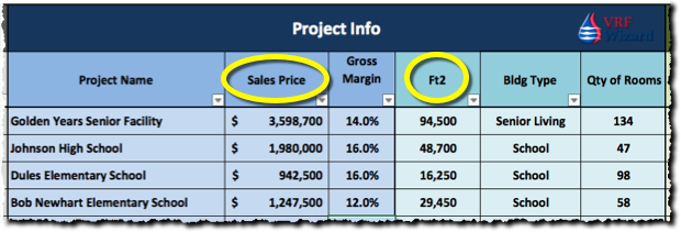
VRF Project Bid Results

Keeping track of the winning bid, will help you stay abreast of market values.

  • How much did the project sell for?
  • How much per ton or per square foot did it sell for compared to what you figured?
VRF Bid Results
VRF Bid Results – VRF Project Cost Tracking Spreadsheet

Scope Included

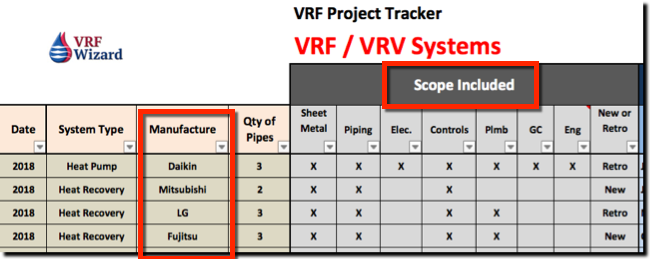
The VRF Project Cost Tracking Spreadsheet will help you quickly sort for projects that are similar in scope to the one you may need to budget or bid. Just check the boxes for the scope included. Everything from Sheet Metal, Piping, Electrical, Controls, Plumbing, General Construction, Engineering and if the project is for Retrofit or NEW Construction. This section

VRF Scope
VRF Scope Included – VRF Project Cost Tracking Spreadsheet

VRF Manufacture

Knowing the manufacture allows you to quickly sort for all the projects containing Mitsubishi, Daikin, LG, Fujitsu, Carrier, or any of the others.

System Type

Tracking the type of VRF systems, whether Heat Recovery or Heat Pump is important as they one has more components then the other which effects cost.

General Construction

Some renovation projects may require the mechanical contractor to provide a turn-key proposal. This is a proposal that covers the cost of all trades and services to complete the full scope of work required to install a new VRF/VRV system. This work will often require you to pour concrete pads for the outdoor units, remove and replace ceilings to hang indoor units, paint walls, etc.

VRF Project Information

This section tracks the Project Name, Sales Price or Bid Price, Gross Margin %, FT2, Building Type & Quantity of Rooms.

VRF Project Info
VRF Project Info – VRF Project Cost Tracking Spreadsheet

VRF Equipment Cost Variables

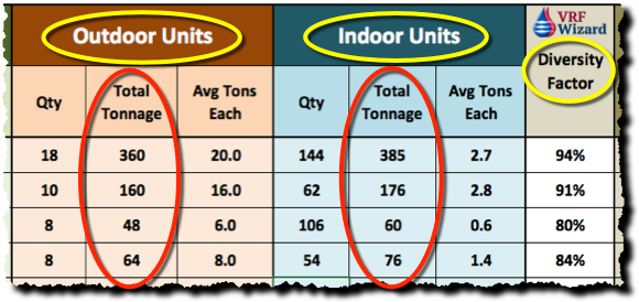
System Diversity Factor

Tracking Diversity Factor will help indicate between projects being compared whether one has a greater diversity factor. This would indicate that one project has more Indoor Unit Tons to Outdoor Unit Tons then the other. Diversity allows you to use less Outdoor Unit Tonnage then Indoor because not all of your Indoor Units will require cooling or heating at the same time. Each zone or Indoor Unit will have a different time of month and day at which they will hit their peak load.

Tracking the quantity of main controllers and adapters or other control components that increase the cost of one project compared to another. One project may require more controllers and the capability to connect to an existing or new BAS system with BACnet capabilities.

VRF Outdoor and Indoor Unit
VRF Outdoor and Indoor Unit – VRF Project Cost Tracking Spreadsheet

Diversity Factor

This factor indicates the capacity of the Outdoor Units to the Indoor Units. A percentage below 100%, indicates that the Total Tonnage of the Outdoor Units is less than the total tonnage of the Indoor Units. The reason that the Outdoor Units usually total less that the total of all the Indoor units is because that the Indoor Units are sized for their PEAK LOADS. The diversity factor indicates that the Indoor Units will not all peak at the same time, so there is no need to size the Outdoor Units to handle the peak load. The Outdoor Units are sized to handle the block load.

Budgeting with the VRF Project Cost Tracker Spreadsheet

Below is an example on how you can quickly budget a VRF project using the VRF Project Cost Tracking Spreadsheet.

EXAMPLE #1

Information Given: 30,000 Ft2 Office, Single Story

STEP #1 (Determine Tonnage)
Determine Tonnage Using VRF Project Cost Tracker Spreadsheet (Engineering Data);

30,000 Ft2 / (500Ft2/Ton) = 60 Tons

STEP #2 (Determine Cost based on $/Ton)
Determine Sells Price using the VRF Project Cost Tracker Spreadsheet;

60 Tons x $15,000/Ton = $900,000

STEP #3 (Determine Cost based on $/Ft2)
Determine Sells Price using the VRF Project Cost Tracker Spreadsheet;

30,000 Ft2 x $29/Ft2 = $870,000

Price Range $870,000 to $900,000

When you keep track of all the information in a VRF spreadsheet, doing budgets and checking bid prices becomes a quick and easy task, saving you time and money. The examples here are simplified, as you would make sure the values you use match the comparable project as close as possible.

The above are just examples are not to be used for actual project pricing.

Who is this VRF Project Cost Spreadsheet for?

If you are a Contractor, Engineer, Distributor or Consultant that has anything to do with VRF/VRV system, then this spreadsheet is for you. By keeping track of the various cost that impacts a VRF/VRV project you will be able to provide quick budgets, do sanity checks for current VRF project proposals, track the cost per ton of VRF equipment and compare the variables that effect these projects.

How do you quickly Budget VRF Projects?

How do you track VRF Project cost and engineering parameters?

Get YOUR VRF Spreadsheet Now >>> VRF Project Cost Tracking Spreadsheet.

Currently only $249.00 $149.00

ZoomLock Cost Analysis

0
ZoomLock Fitting Cost Analysis

ZoomLock Cost Analysis

Determining if there is value in using a press-fit joint such as ZoomLock™ requires that you look at several factors that impact cost and quality. We covered the technical aspects of ZoomLock™ in another article; see ZoomLock vs Brazed for additional information. In this article we are strictly looking at this from a financial perspective. We try to answer one question in this ZoomLock Cost Analysis, ‘Does ZoomLock make financial sense for your business?

(Click here to enlarge Infographic)

ZoomLock Fitting Cost Analysis Infographic

Share this Image On Your Site

ZoomLock Value Calculator

Be careful when using the online downloadable ZoomLock™ value calculator as it appears to us that they have over inflated the time it takes to make a brazed joint. They are showing that the ZoomLock joints take about 25% of the time as a brazed joint, or the equivalent of a 75% savings. This even contradicts their literature that claims a 60% savings.

There are also many versions of the ZoomLock Calculator available when doing a Google search. Here are two versions of them;

1) http://sporlanonline.com/zoomlock/value-calculator/ (2017 version)
2) ZoomLock Value Calculator 2016 (Direct download of an Excel file) Google for file.

The ZoomLock calculator also uses $95/Hr for brazing and $75/Hr for their fitting. This reflects the lower skill level required to make a ZoomLock joint compared to that for a brazed joint.

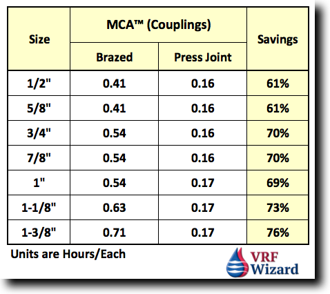
When I look at the MCA database and do the calculations I find a different value, ranging from 61% to a 73% savings based on size. This is strictly based on the labor unit values in the MCA database for “OD Size Wrot/Cast Copper Fittings” and “Ridgid ProPress”. MCA doesn’t have ZoomLock values, so ProPress values are used which is basically the same setup and procedure for a press-fit joint. For our example I’ll use “Couplings” (Unit values are in hours/each fitting)

ZoomLock Labor Units - MCA
ZoomLock vs Brazed MCA Labor Units

One of ZoomLock’s online video’s shows that they can do 8 joints to a single brazed joint, which implies an 87% savings. There appears to be some inconsistency in ZoomLocks marketing on their websites, downloadable calculator and various publications of just how much labor you can save using their fittings, but there is no denying the fact that you will save time with their system.

It’s important to establish the basis’s of comparison and the unit values that are used in any analysis. We’ll use a 60% savings in our cost analysis as this matches the MCA database and ZoomLock’s published data. It’s also important to note that your values will differ based on the skill level of your installation personnel. The unit values above have assumptions based on standard working conditions, and the unit values include receiving, unloading, stockpiling, distribution, handling and erection, fitting and joining and pressure testing.

MCA – Mechanical Contractors Association

For those of you who are unfamiliar with MCA (Mechanical Contractors Association), they are an industry organization who as part of their service provides publications, training and a database of labor units garnered through contractor surveys. If you own a commercial HVAC company and use estimating software for piping takeoff’s, then its most likely that you have the option of using MCA as a choice for your labor unit values.

ZoomLock™ Fitting & Labor Cost

In our ZoomLock Cost Analysis we look at the two main costs that impact the financial decision on whether to use ZoomLock™ fittings, one is labor and the other is the cost of the fittings and tools. The cost of the fittings differs from the cost of the tools in that the fittings are a direct cost charged to a certain project, while the tools are a capital asset that can be used on multiple projects and will be depreciated over time.

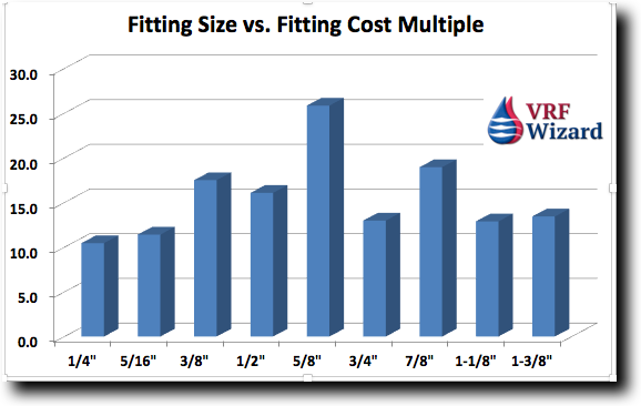
ZoomLocks Value Calculator (2017 Version) shows that their fittings cost anywhere from 11 to 24 times that of an OD wrot copper fitting, your cost could be different based on your companies buying power and the discount your supplier provides you. Their average cost is 15x times that of a brazed fitting. We’ll use an average of 14 times for this example.

ZoomLock Fitting Price Analysis

ZoomLock™ Installed Cost

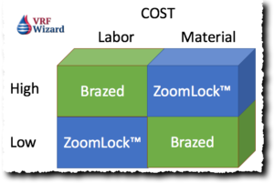
Comparing ZoomLock™ to Brazing reveals that at some point there will be an intersection or breakeven point between the two systems. In the situation where labor rates are low, the extra cost of the ZoomLock™ material will dictate that brazing is more cost effective. Likewise, as the labor rate increases, the cost of labor becomes the overriding factor, making ZoomLock™ the more cost effective solution due to its labor saving features.

ZoomLock™ Breakeven Point

The breakeven point is determined by three factors; material cost, labor rate and labor productivity. The breakeven point will differ from one company to another based on these factors. The two main variables are your company’s purchasing power with your vendor and the labor rates for field installation personnel. Your labor productivity should be close to the industry norms. The example in the chart shows a $35/hour breakeven point, which means anything above that crew rate for your installers would make ZoomLock™ financially viable. This is just an example and your breakeven rate will differ. Just realize that the breakeven point is going to be much higher than $35/hour for most companies. This example is strictly based on a financial analysis, exclusive of all the other benefits of using a non-flame fitting as discussed in a previous article. The breakeven point changes when you change the variables in the ZoomLock Value Calculator.

ZoomLock Cost Analysis
ZoomLock Fittings Breakeven Analysis

Fitting Cost Variance

Based on which size fittings are part of your project, the cost various. The most common and highly manufactured OD Wrot Copper brazed fittings drop in price based on size, so a larger fitting size could actually be less costly than a smaller fitting. In these cases the cost difference between ZoomLock™ and brazed fittings increases, causing the chart below to look more like a stock on Wall Street than a straight line. This is shown by looking at the 5/8” fitting size to notice that the difference between ZoomLock™ and brazed is at its greatest. ZoomLock™ fittings increase in cost sequentially with the fitting size.

ZoomLock Fitting Sizes vs Cost Multiplier

Other Considerations

Since this report is based solely on a financial decision we won’t go in depth on the other considerations when making a decision to use ZoomLock™. Putting cost aside there are many benefits to the use of ZoomLock™ or press-fit fittings when installing refrigerant piping. Labor is the obvious advantage, but others such as we covered in our previous article entitled “ZoomLock vs. Brazed”. These advantages include no need for a hot working permit, reduced risk of fires from a brazing torch, no smell from a torch or the accidental setting off of smoke detectors, or the use of a nitrogen purge.

Summary

Our ZoomLock Cost analysis believes that ZoomLock is a financially viable alternative when labor rates and labor productivity are high enough to offset the additional cost of the special fittings. The breakeven point is determined by the cost of material, labor rates and labor productively. The analysis doesn’t take into consideration varying jobsite conditions that could make either of the options undesirable for many reasons, such as space restrictions, building construction material types, occupancy type and facility protocols when using an open flame tool.

ZoomLock Fittings vs Brazed

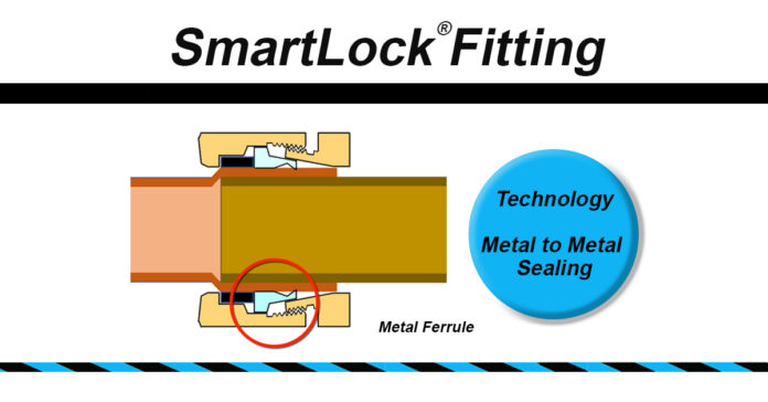
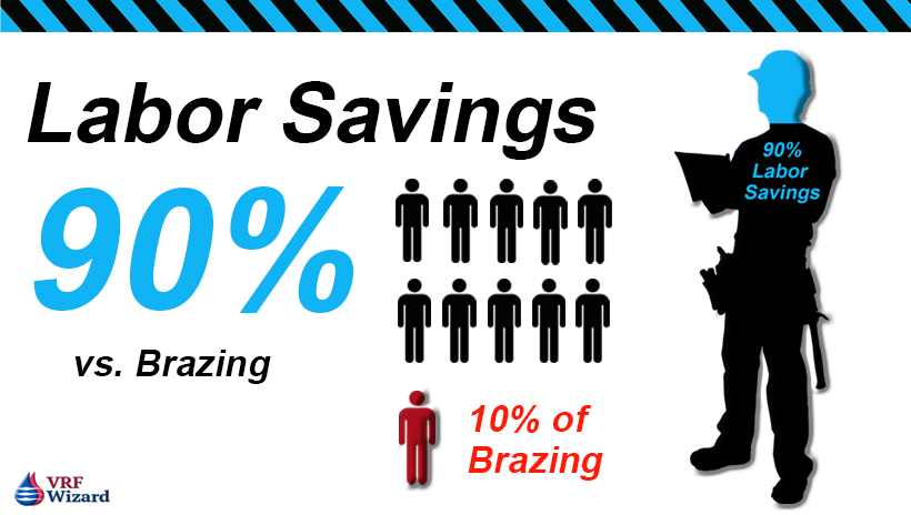
Based on our ZoomLock Cost Analysis we definitely recommend that you call your local ZoomLock™ distributor and get a free demo, it just may be the next generation of joints with the greatest growth potential, and if your customer has seen an advertisement about it and is more aware then you are, that’s embarrassing. Also, see the SmartLock Fitting for additional labor savings according to its manufacture.

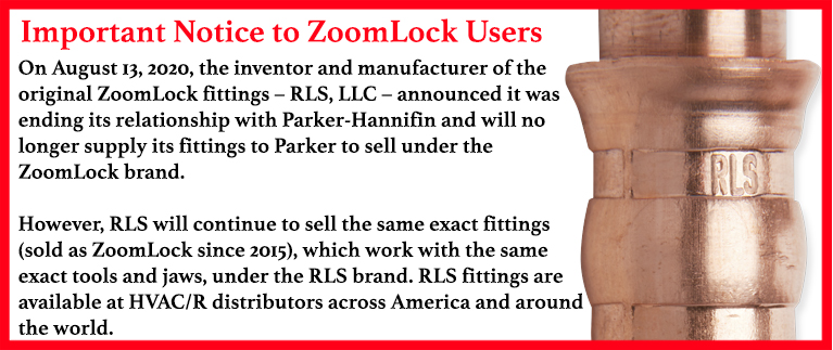
Important Notice for ZoomLock Users

Checkout ASHRAE’s study on Mechanical Piping Joints.

For additional information see our article ZoomLock vs Brazed Fittings or our review of the ZoomLock Value Calculator and our ZoomLock Klauke 19 kn Tool Review

Also check out our article on the Lokring Pressfit Fitting , SmartLock Fitting and Reftekk Bendable Piping.

HVAC Estimating spreadsheet

Subscribe to our mailing list

* indicates required


VRF Manufacture Comparison

0
VRF Manufacture Comparison, Daikin, Mitsubishi, LG, Toshiba, Carrier, Trane, Fujitsu, Panasonic, Hitachi

VRF Manufacture Comparison

With so many VRF manufactures to compare, it’s hard to decipher all the variations between systems. Below you’ll find a comparison of VRF manufactures such as, Daikin, Mitsubishi, LG, Carrier, Toshiba (Carrier), Fujitsu, Panasonic, Hitachi (York) and others to follow. We will be adding additional VRF Manufacture Comparison charts in the following weeks.


VRF Maximum Cooling Capacity

The following chart indicates the maximum cooling capacity in tons and 1,000’s of BTU for both VRF Heat Recovery Systems and VRF Heat Pump Systems.These values are based on multiple outdoor unit modules being attached to makeup the maximum, often three ODU.

Maximum Cooling Capacity – (Tons)

System Daikin Mitsubishi LG Carrier Toshiba Fujitsu Panasonic Hitachi York
Heat Recovery 38 24 42 28 38 24 30 36 36
Heat Pump 34 30 42 36 38 24 30 36 36

Maximum Cooling Capacity MBH – (1,000’s of BTU’s)

System Daikin Mitsubishi LG Carrier Toshiba Fujitsu Panasonic Hitachi York
Heat Recovery 456 288 504 336 456 288 360 432 432
Heat Pump 408 360 504 432 456 288 360 432 432

VRF Maximum Piping Lengths

The following chart indicates the maximum piping lengths that is approved by the various VRF manufactures in order that the system perform as designed. Confirm with manufacturers literature as there are often limiting factors effecting these lengths. Some manufacturers show equivalent length which means the actual distance is less, but that a fitting is added in as an equivalent length of pipe.

Total Maximum Piping Length – Between ODU & IDU (Feet)

Daikin Mitsubishi LG Carrier Toshiba Fujitsu Panasonic Hitachi
TBD 541′ 656′ 541′ 656′ 541′ TBD TBD

Maximum VRF Indoor Units Attached to ODU’s

The following chart indicates the maximum quantity of VRF Indoor Units that can be attached to a set of VRF Outdoor Units. VRF Manufacturers connect several Outdoor Units together using various module sizes (tons) to comprise the maximum tons, often composed of three to four modules. This chart shows the maximum number of Indoor Units that can be connected to those connected Outdoor Modules.

System Daikin Mitsubishi LG Carrier Toshiba Fujitsu Panasonic Hitachi York
Heat Recovery 64 50 64 64 64 45 52 TBD 64
Heat Pump 64 50 64 62 64 45 64 TBD 64

VRF Single-Port vs Multi-Port Branch Selector Box*

The following chart indicates if the VRF manufacture has a single-port branch selector box, as all VRF manufactures carry the Multi-port Branch Selector Box for their Heat Recovery systems.

System Daikin Mitsubishi LG Carrier Toshiba Fujitsu Panasonic Hitachi York
Single Port Yes No No No Yes Yes Yes TBD Yes
Multi Port Yes Yes Yes Yes Yes Yes Yes Yes Yes

* Fujitsu uses (RB) Refrigerant Branch Unit as the name for their Branch Selector box, Mitsubishi use “BC Controller”, Branch Circuit Controller, Toshiba calls their boxes “Flow Selector Unit”, Hitachi (COB) Change-over Box,


VRF Heat Recovery Branch Selector Box

The following chart is a comparison of HVAC VRF manufactures options and capacities for their VRF Heat Recovery Branch Selector Boxes.

System Daikin Mitsubishi LG Carrier Toshiba Fujitsu Panasonic Hitachi York
Max Capacity 290 120 192 TBD 96 96* TBD 272 TBD
Max 1-Port  54 TBD 54 TBD TBD 96 TBD TBD TBD
Max Ports 12 TBD 4 TBD 6 4 8 12 12

Max Capacity = The maximum capacity in MBH (1,000’s of BTU’s) for the VRF manufacturers largest box.
Max 1-Port = The maximum capacity out of one port on the multi-port box.
Max Ports = The maximum number of ports on one box.

* Some HVAC VRF Manufactures allow you to connect several branch selector boxes in series to increase capacity. Fujitsu allows two RB Units to be attached to increase the maximum capacity to 191 MBH. Mitsubishi allows the connection of Sub BC Controllers to increase capacity.


*TBD – To Be Determined at a Latter date

VRF HVAC Cost Budgeting Spreadsheet

Leave us any comments related to the enclosed charts or any other HVAC VRF manufacture comparisons you would like to see.

Subscribe to our mailing list

* indicates required


VRF Case Studies USA

0
VRF Case Studies

VRF Case Studies USA

The following links are for VRF case studies USA from various VRF manufactures. Also see the following for links to VRF Project Videos or VRF Case Studies International and VRF International Project Videos

Sorted by VRF Project Type

Airports

  1. NW Florida Beaches Intl Airport – LG VRFPanama City Beach, Florida
  2. March Air Reserve Base – Toshiba VRFRiverside, California

Church

  1. Redeemer Lutheran Church – Daikin VRVWinter Park, FL (VRV-III)
  2. Grace united Methodist – Trane VRFHastings, Nebraska (Trane Advantage)
  3. First Presbyterian Church – Daikin VRVDeland, FL (28-Tons Heat Pump VRV-III)
  4. Asbury United Methodist – Mitsubishi VRFVirginia (23,000 Ft2)
  5. Our Lady of Florida – Daikin VRVWest Palm Beach, FL (Water-Cooled)
  6. Stetson Baptist Church – Daikin VRV – Deland, FL (30-Tons)
  7. Lord Street Synagogue – Daikin VRVBaltimore, MD (28-Tons Heat Pump VRV-III)
  8. Valley Point Church – LG VRF – Glen Mills, PA (16,000 Ft2, 50-Tons)

Hotels

  1. Imperial Hotel – LG VRFAtlanta, Georgia (Multi-VIII Heat Recovery)
  2. Hampton Inn 17-Story – LG VRF Chicago, IL (VRF Heat Recovery)
  3. Bicycle Hotel & Casino – Mitsubishi VRF Bell Gardens, CA (183 Ductless Units)
  4. Embassy Suites Airport – Daikin VRVRaleigh, NC (212-Tons Heat Recovery)
  5. Herlong Mansion Historic Inn – Daikin VRVMicanopy, FL (Heat Pump)
  6. The Marlton Hotel – LG VRF – New York

Medical Centers & Hospitals

  1. Trinity Medical Center 90,000 Ft2 – LG VRFTrinity, Florida (Multi-VII)
  2. Assisted Living Facility – Daikin VRVBlack Mtn, NC (Heat Pump 32-indoor Units)
  3. Assisted living Facility, The Meadows – Daikin VRVTewksbury, NJ (Heat Pump)
  4. Post Falls Periodontics – Daikin VRVPost Falls, ID (VRV-III Heat Recovery)
  5. David Whitney Building – Mitsubishi VRFDetroit, MI (600+ Tons)

Office Buildings

  1. 10-Story Office – LG VRFSoho West, New York (Multi-VIII Heat Pump)
  2. Comflow Office – Daikin VRVHouston, TX (4,500 Ft2 VRV-III Heat Recovery 16-Tons)
  3. Sidney Credit Union – Daikin VRVSidney, NY (Water-Cooled Heat Recovery)
  4. Western Extralite – Daikin VRVLawrence, KS (VRV-III Heat Recovery)
  5. ASHRAE Headquarters – Daikin VRVAtalanta, GA (VRV-III Heat Recovery)

Residential & Apartments

  1. 464 Unit High-Rise Apartment – LG VRF – Los Angeles, California (Multi-V)
  2. 4500 Ft2 Home – LG VRFTampa, Florida (Multi-Zone)
  3. This Old House – Daikin VRVWeston, MA (3,800 Ft2, VRV-S)
  4. Bakken Residence – Mitsubishi VRFHawaii (10,980 ft2 Home + 2,000 Battery Storage)
  5. Domsey Condo’s – Mitsubishi VRFBrooklyn, New York (280,000 Ft2)
  6. Discovery at the Realm – LG VRFLewisville, TX (672 Tons)
  7. The Mackie Building – LG VRF – Milwaukee, WS (Mixed Use)

Restaurant

Fogo de Chao Restaurant – Mitsubishi VRF – New York City, NY (84 Tons)

Retail

  1. YMCA Deland – Daikin VRVDeland, Fl. (102-Tons, 46 Fan Coils)
  2. Marcel’s Supermarket – Daikin VRVHouma, LA (VRV-III Heat Pump)
  3. Stella Wine Tasting – Daikin VRVDundee, OR (VRV-III Heat Pump – Solar)

Schools

  1. Sprout Space – LG VRFWashington, D.C.
  2. Albert Einstein Academy – Toshiba VRFSan Diego, California (Heat Recovery)
  3. Shannon Learning Center – Daikin VRFDallas, Texas (Heat Recovery)
  4. Burton Center for Arts & Tech – Mitsubishi VRFSalem, Virginia (20,000 Ft2)
  5. West Hernando Middle School – Daikin VRV Brooksville, FL (Heat Recovery & DOAS)
  6. Bayless High School – Daikin VRVAffton, MO (110,000 Ft2 Heat Recovery & HP)

Subscribe to our mailing list

* indicates required


VRF Project Videos – USA

0
VRF Project Videos

VRF Project Videos

Below are links to VRF project videos based on building type and VRF system description. Clink on the building name to watch a video about the project.

We also have a list of VRF Case Studies spotlighting various building types. These videos and project profiles are great for customer presentations to show project that have adopted this technology. We also have a list of VRF International Project Videos or VRF International Case Studies.

Airports

  1. March Air Force Base – LG VRF – Riverside, California, USA

Church

  1. St. James Church – Fujitsu VRF – Raleigh, NC, USA
  2. St. Dominic’s Convent – Fujitsu VRF – Blauvelt, NY, USA

Hotels

  1. Hampton Inn (VRF Art Cool Mirror Units) – LG
  2. The Marlton Hotel (LG VRF)

Mixed Use

  1. The Mackie Building – LG VRF – (55,000 Ft2) Milwaukee, Wisconsin
  2. Columbia Square – Los Angeles, CA – LG VRF

Residential – Homes, High-Rise Apartments 

  1. Phoenix Home – Fujitsu VRF – Phoenix, AZ, USA
  2. The Sharpe Building LG VRF (VRF Heat Recovery System) – High-Rise
  3. Tabco Towers – Fujitsu VRF – Residential High-Rise
  4. US Vermont – LG VRF – (VRF Heat Recovery System) – High-Rise, Mixed Use
  5. Discovery at the Realm – Texas – Mixed Use LG VRF – Vertical AHU

Restaurants

  1. Cornish Pastry Restaurants – Fujitsu VRF – Phoenix, AZ, USA

Schools

  1. SMouse Opportunity School (VRF Heat Recovery System) – LG
  2. Albert Einstein Academy Middle School (VRF Heat Recovery System) – Toshiba
  3. Shippensburg University – Panasonic VRF – Shippensburg, PA

Senior Living Facility

  1. Senior Living Facility – Panasonic VRF – Fort Myers, FL (ECOi VRF System)

Storage Facility

  1. Storage Facility – Panasonic VRF – Columbia, SC

HVAC Estimating spreadsheet

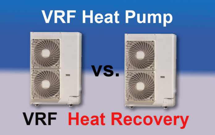
When to use a VRF Heat Pump vs VRF Heat Recovery System

0
VRF Heat Pump vs Heat Recovery

VRF Heat Pump or Heat Recovery (How to choose between a VRF Heat Pump or Heat Recovery System) or Packaged DX

Scroll to the bottom if you prefer to watch the video.

VRF systems are responsive to variations in cooling and heating demand as compared to the traditional AC unit that has a fixed speed compressor and fan. VRF system provide for varying the energy consumption by varying the speed of the compressor or outdoor unit fans based on the demand. If the traditional packaged or split system DX units are oversized, they’ll short circuit on and off.

How do you determine which system to use for a particular building or space type? Is a VRF Heat Pump or a Heat Recovery System better than a conventional Packaged DX unit? 

Of course, VRF Heat Recovery Systems are a little more complex and cost more than a heat pump or traditional DX unit. But when do you choose one system over the other? So, how do you decide if a VRF system is feasible for your project?

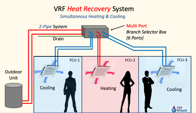
VRF Heat Recovery System with Branch Selector Box

Some of the key items to look for when deciding are the owner’s requirements, zoning layout, building orientation, the need for simultaneous heating and cooling, the space available for running piping or ductwork, ventilation requirements as mandated by code and building profile.

Energy Efficiency

One of the benefits of a VRF system over the traditional DX packaged or split system is that it runs on less energy. Because the variable speed compressor can ramp up or down with demand, which makes it more efficient that the on/off style of the standard compressor in a DX system. This allows the compressor to run at part load where it is more efficient. Also, the outdoor fan may have the option of also ramping up and down with demand.

Ventilation Requirements

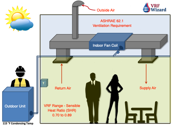
ASHRAE Standard 62.1, Ventilation for Acceptable Indoor Air Quality, and any local building codes will define the fresh air requirements for the occupancy type. There are many approaches to this depending on the quantity of ventilation air required to each space and the design outdoor conditions. 

VRF Ventilation per ASHRAE 62.1

In high humidity locations the need to precondition the air to remove moisture will need to be considered as the VRF fan coils can handle only a small amount of latent. See the sensible heat ratio for the VRF manufacture that you’re considering. See our article on DOAS units that serve the function of providing code required ventilation air and the various methods to do so.

With Packaged DX units outside there is no need to worry about ducting ventilation air. This requirement arises anytime you use a split system of any kind.

Heating and Cooling Simultaneously

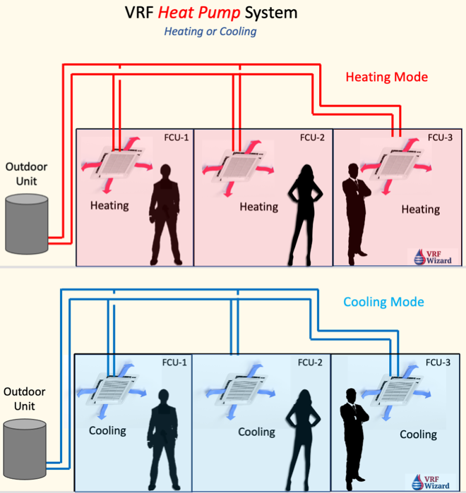
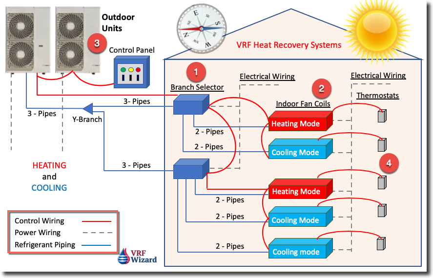
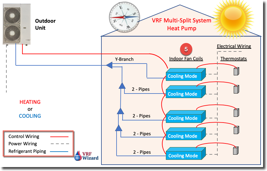
This is the defining question when it comes to the type of VRF system to use. A VRF Heat Pump system doesn’t provide simultaneous heating and cooling. With a VRF Heat Pump you must have all the connected zones (Indoor Fan Coils) in either heating or cooling mode. Using a VRF Heat Recovery system allows you to have simultaneous Heating and Cooling to the various zones being fed from the same outdoor unit(s). 

If the layout allows and the orientation and zone configurations are similar, you may be able to combine zones and use a VRF Heat Pump system. If you can provide a Heat Pump instead of a Heat Recovery system, then you can reduce complexity and cost. You will need to consider how the spaces are configured and if they share the same orientation to the sun and will experience similar thermal loading. If the zones don’t have similar orientation, then that’s when you’ll need to either make smaller VRF Heat Pump zones that are similar in load profile or use a VRF Heat Recovery System. You can see in the image below that with a heat pump system you’ll have all zones in Heating or Cooling, there is no simultaneous heating and cooling.

VRF Heat Pump System

The reason this is important is that when the sun is shining brightly on the south glass, those exterior spaces will require cooling, while the north exposure may require heating because its shaded and much cooler. These zones would require simultaneous heating and cooling or separate systems. The same can be said of mixing interior with exterior zones, the exterior zone is dependent on the varying outside weather conditions, while the interior is usually consistent in its load profile.

If the cooling and heating load profile is somewhat balanced than this could be a good candidate for a VRF Heat Recovery system. With a Heat Recovery system, you can move heat around from a zone that wants cooling to a zone that wants heating. This is an efficient use of energy, in lieu of rejecting the heat to the outdoors in a conventional DX unit and then using some other form of heating source to provide heat.

When using a heat pump or heat recovery system, the designer needs to ensure that the minimum amount of heat is available when the outdoor temperature drops below the VRF manufacturers catalogue value. The catalogue will indicate the capacity for heating at some stated outside air temperature. In colder climates the designer must ensure that the VRF unit will be capable of maintaining the desired heating. See the derated values in the VRF manufactures catalogue for lower outdoor temperatures. If heating demand is higher than some form of supplemental heating can be provided.

Branch Controllers (Box Selectors)

The terminology for what is considered the refrigerant traffic monitor varies with each VRF manufacture. This is the selector box (Branch Controller) required for a VRF Heat Recovery system that directs the flow of refrigerant based on whether the zone is calling for heating or cooling. When using a VRF heat recovery system which is more expensive than a VRF Heat Pump system you’ll have the added cost of providing electrical to these boxes. Some VRF manufactures also require a condensate drain piping off their branch controllers. (see image above)

Sizing the Zones (Indoor Units)

The predominate load profile of either the cooling or heating will dictate how the indoor unit is selected. In extreme cold climates the indoor unit maybe selected based on its heating capacity to ensure that the maximum amount of heating is available. If the designer were to choose the indoor unit based on the cooling load in a location with very cold winters, then the heating capacity may fall short of the space requirement for heating. So, its’ imperative to select the indoor unit based on the maximum of either the cooling or heating, whichever is greater.

Based on the style of indoor unit, that is, if its ducted or non-ducted, you may be able to combine multiple spaces of the same thermal profile and exposure. The owner or Architect may have requirements about aesthetics if you are thinking of using any of the wall or ceiling mounted fan coils that are visible to the occupants.

The outdoor unit will be selected based on the Block Load of the building. The block load is the maximum combined peak load of all the zones at a given time of day. The total Btu’s would total up to an outdoor unit that is smaller than the total peak load of all the indoor units.

Occupancy Schedule

Depending on the type of facility there can be a wide variable in the time spaces are used. For instance, a school mostly has the same hours of operation for each classroom, while high occupancy areas such as assembly halls, conference rooms and meeting rooms can vary widely on time of use. You wouldn’t put these varying use schedules on the same zone. Rooms with large latent loads (moisture) caused by occupants or equipment will need to be closely looked at to ensure the latent load can be handled by the system. Remember that most VRF systems have high sensible heat ratios (SHR), which means they don’t deal efficiently with too much latent load.

VRF System Cost

As mentioned previously the VRF Heat Recovery system is going to cost more  when compared to a VRF Heat Pump or Conventional DX unit. These additional cost we’ll have to be compared against any energy savings or system benefits. There are some cases where the added cost makes sense and for which a thorough analysis of the space requirements is required. If you are an HVAC contractor or Engineer that tracks the cost of VRF Systems, then see our VRF System Cost Spreadsheet for keeping track of these type of projects.

VRF System Cost Spreadsheet by the VRF Wizard

Space Requirements

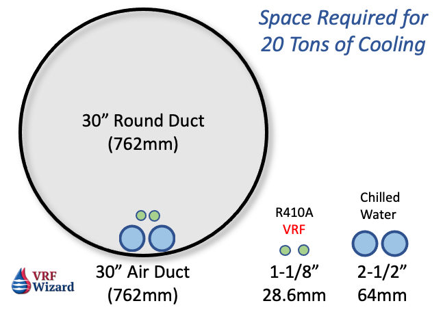
VRF systems or split systems in general are great for retrofit projects because they’re less invasive to the existing conditions. It’s easier to route small copper piping through an existing structure then to route air ducts of the same capacity.

Space Required for 20 Tons using Air, Refrigerant or Chilled Water

You’ll need space in the attic or ceiling for any selector boxes (branch controllers) when using a VRF Heat Recovery system.

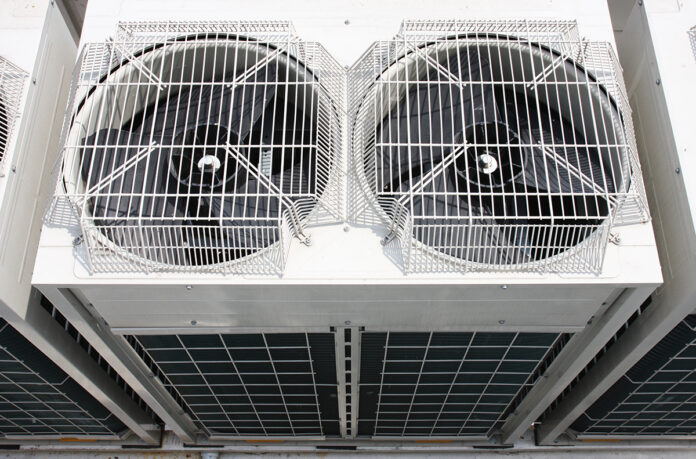
All systems will need space on the ground or roof for the outdoor unit. Packaged DX units will take up the most space because all its components are in one box.

Electrical

A conventional rooftop DX unit is the simplest when considering electrical connections as there is only one point of connection. When using a VRF Heat Recovery system you’ll need at least three points of connection, the Outdoor Unit, Indoor Unit and Selector Box. With a VRF Heat Pump you’ll have two connections, the Outdoor Unit and Indoor Unit.

This doesn’t include small split systems where the outdoor unit comes with power wiring that feeds the Indoor unit, hence one connection.

  • Packaged Unit – 1 Connection
  • VRF Heat Pump – 2 Connections
  • VRF Heat Recovery – 3 Connections

VRF Piping Limitations

Depending on the building configuration and where the outdoor units can be located, each VRF manufacture has limits to the distance piping can be between the outdoor units and the furthest indoor unit. This distance is calculated vertical as well as the overall distance between the outdoor and furthest indoor fan coil.

Of course even the standard DX split system has piping limitations that if exceeded degrades the tonnage.

Conventional DX System

If you choose not to use a VRF system, then you’ll need to consider other factors. Is there space on the roof for packaged DX equipment? Can the roof structure support the added weight, or will structural reinforcement be required? Is there space to run the ductwork from the packaged unit to the area it will serve? 

A VRF system can carry more tonnage in a smaller space by using refrigerant piping to cool a space in lieu of ductwork from a packaged DX unit.

Remember also that you can use a mixture of VRF and conventional packaged DX systems to meet any project requirements. It’s not all or the other, as often designs will use the different benefits each of these systems brings to a project.

Summary

Using a VRF system is a good choice for many reasons but deciding on whether to use a straight VRF Heat Pump versus a VRF Heat Recovery system requires some additional analysis. If the decision is left up to you, then here are some questions you should ask yourself when considering whether to use a VRF system and which type to use.

RF System Comparison Chart
VRF System Comparison
  • Can the zones be separated into similar exposure or heat gain profiles?
  • Do the zones need simultaneous heating and cooling capabilities?
  • Is cost a major consideration?
  • How will you get code required ventilation to the space, and does it need to be preconditioned?
  • Is there space for ducted fan coils and Selector Boxes (Branch Controllers) in the attic or ceiling space?
  • What type of space is there for outdoor units?
  • What is the occupancy schedule for the various spaces?
  • Do the spaces meet the requirements for ASHRAE 15? (See our article on ASHRAE 15 & xxx)
  • Will you need refrigerant monitoring?

VRF Compressor Types

0
VRF-Compressor-Types

The compressor is the heart of the system and is located within the Outdoor Unit which can be an air or water-cooled VRF system. The Outdoor Unit will serve multiple indoor units with each VRF manufacture limiting the quantity of indoor units connected to any combination of Outdoor Units. The VRF system varies the flow of refrigerant to each of the connected indoor units based on the needs of that unit, allowing the system to adjust the volume (flow) based on demand. 

Each indoor unit uses an expansion valve to control its refrigerant supply to match the cooling / heating demand of the space it serves. The outdoor unit also varies its output to match the total demand of the indoor units. – Danfoss

The compressors come in various quantities and types based on the VRF Manufacture and system tonnage. The most used VRF compressor types are the Rotary and Scroll Compressors. 

VRF Rotary Compressors

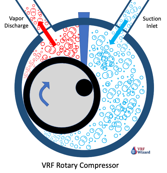
VRF Rotary Compressor Image
VRF Rotary Compressor

The heart of the rotary compressor is the cylinder which houses the piston and the vane. The vane maintains constant contact with the piston as the piston rolls along the inside wall of the cylinder. As the piston rotates, gas is compressed into an increasingly smaller area until the discharge pressure is reached, releasing gas into the shell chamber. At the same time, more gas comes in through the suction port, enabling a continuous process of suction and discharge.


The simple design and symmetry of the cylinder components, combined with a special coating and premium materials, provide a highly durable and reliable product, rotation after rotation. – Panasonic3

Toshiba Twin Rotary Compressor

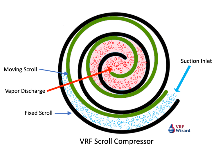
VRF Scroll Compressor

The first scroll compressor for Air Conditioning was produced in 1983 by Hitachi, so scroll compressors have been in development for a long time. These first scroll compressors were most likely constant speed. Copeland states in their literature that they have been developing the scroll compressor since 1979.1

There are two basic types of scroll compressors in use, the ‘Digital Scroll” and the “Inverter Scroll.”

VRF Inverter Scroll Compressor

VRF Inverter Scroll Compressor

The Danfoss inverter compressor solution for commercial HVAC applications allows a VRF system to modulate the cooling capacity precisely between 25% and 100% when a single compressor is used, and between 12.5% and 100% with tandem compressors (Modulation range for VZH compressors). The unit adjusts to the varying loads that the building needs during the day. 2

VRF Digital Scroll Compressor

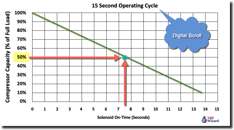
The Copeland Scroll Digital compressor is capable of modulating its capacity from 10% to 100%. The compressor is supplied along with an external solenoid valve. This “normally closed” (deenergized) solenoid valve is a key component for achieving modulation. When the solenoid valve is in its normally closed position, the compressor operates at full capacity. When the solenoid valve is energized, the two scroll elements move apart axially. 

During the unloaded state, the compressor motor continues running, but since the scrolls are separated, there is no compression. During the “loaded state”, the compressor delivers 100% capacity and during the “unloaded state”, the compressor delivers 0% capacity. A cycle consists of a “loaded state” and an “unloaded state”. By varying the time of “loaded state” and “unloaded state”, an average capacity is obtained. For instance, in a 20-second cycle, the average capacity is 75%, if the “loaded time” is 15 seconds and the “unloaded time” is 5 seconds. – (Copeland Scroll Digital, page 6, C6.2.15/0815/E)

By controlling the capacity with a solenoid valve the VRF Compressor motor avoids the unnecessary wear caused by frequent start and stop cycles. This method is 30% more efficient then Hot Gas Bypass or Suction Throttling.

VRF Digital Scroll Compressor Capacity per Cycle Time Chart
VRF Digital Scroll Compressor Capacity per Cycle Time

As the chart shows above, the longer the Solenoid Valve is on the less capacity the VRF compressor delivers. If the solenoid is open for 7.5 seconds, which equates to half the cycle time (15 sec.), then the compressor capacity is 50% (half).

VRF Compressor Configurations

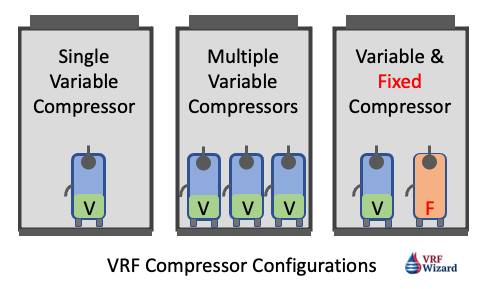
You will find a minimum of three versions of VRF System compressor configurations.

VRF Compressor Configurations

Single Variable Speed Compressor

The compressor will ramp up and down depending on the demand of the indoor units, but won’t have any backup if there is a compressor failure.

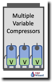
Multiple Variable Speed Compressors

Multiple VRF Variable Compressors Image
Multiple VRF Variable Compressors

These VRF Outdoor Units can contain two or more compressors and provide redundancy if one of the compressors fail. The VRF controller with sequence the compressor for optimum energy efficiency and shared runtime. 
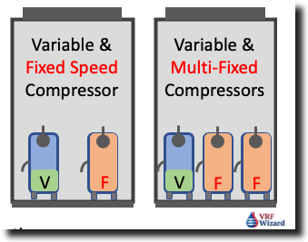
Mixed Compressors – Variable & Fixed Speed

VRF Variable and Fixed Speed Compressors

Various VRF Manufactures use a mixture of variable and fixed speed compressors in their outdoor units to handle the indoor unit demand. VRF manufactures may have two or more fixed speed compressors with one variable speed compressor.

VRF Compressor Duty Cycling

When the VRF system contains more than one compressor or connected outdoor unit, the system has the capabilities of optimizing the run-time of each compressor. This ensures that all the compressors share in the hours of operations instead of using the same compressor each time the unit comes on. This should extend the life of the of the VRF compressors by sharing in the total run hours.

VRF Compressor Duty Cycling Image
VRF Compressor Duty Cycling

Some VRF system compressors will rotate operation between outdoor units to ensure system efficiency and shared duty. This means some outdoor units will be off while others are running, then during the next duty cycle the unit that was off may now be running while the previous unit that was running is off. Various versions of these scenarios are used by the VRF Manufactures to provide optimum efficiency, compressor longevity and proper sharing of the runtime for each compressor.

VRF Compressor Backup Operation

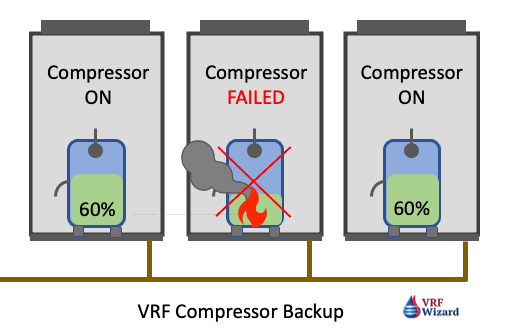
Under the same conditions above where you have multiple Compressors or outdoor units, the VRF system can provide partial capacity in the event that one of the compressors or outdoor unit’s malfunction.

RF Compressor Failure Backup image
VRF Compressor Failure Backup

VRF Outdoor Unit Capacity 

The capacity of the VRF System is rated per AHRI 1230 to establish it’s ‘Integrated Energy Efficiency Ratio (IEER)’ which looks at the summation of four values of various running capacities: 100%, 75%, 50% and 25%, which is one full load condition and three-part load conditions.

IEER – Integrated Energy Efficiency Ratio Formula

IEER = (2% x A) + (61.7% x B) + (23.8% x C) + (12.5% x D)

A = EER at 100% AHRI Standard Conditions (95 F)

B = EER at  75% (81.5 F)

C = EER at  50% (68 F)

D = EER at  25% (65 F)

Efficiencies are higher and energy consumption is lower when running at reduced capacities, so this will be optimized across multiple connected compressors by running them at part loads, before running one compressor at full load. As the IEER formula gives the greatest weight to running at 75% load, followed by 23.8% at 50% load.

Larger capacity systems are achieved by mating several smaller units together.

The use of inverter duty compressors and electronic expansions valves EEV’s provides a method for stable temperatures and pressures in addition to energy savings.

The speed of the compressor will vary based on the cooling or heating demand from each indoor unit which has an expansion valve regulating the flow of liquid refrigerant for cooling or hot gas vapor for heating.

The pertinent information from the positions of the EEV’s and the indoor sensors is communicated to the outdoor unit which makes an adjustment to the volume of refrigerant flowing in the system and the speed of the outdoor fan required to meet the existing conditions, for digital scrolls this would affect the loading or unloading cycle time.

With the Daikin VRV IV system you can choose the temperature response speed, as the outdoor temperature increases so does the evaporative temperature. The response can be very fast (Powerful mode – least efficient), fast (Quick mode) and Medium (Mild Mode – Most energy efficient).

VRF Compressor Manufactures

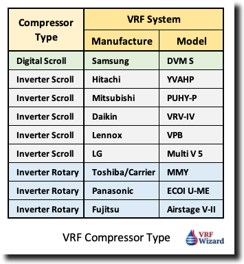
The compressors contained within the Various VRF Manufactures equipment is often manufactured by another company, one that specializes in compressors like Danfoss or Copeland.

VRF Compressor Type per VRF Manufacture

Danfoss is a manufacture of compressors used in various VRF Systems, and according to their statement:

“The Danfoss inverter compressor solution for commercial HVAC applications allows a VRF system to modulate the cooling capacity precisely between 25% and 100% when a single compressor is used, and between 12.5% and 100% with tandem compressors (Modulation range for VZH compressors). The unit adjusts to the varying loads that the building needs during the day.” – Danfoss

Summary

The use of VRF systems and the various compressor types will save on energy and provide the following benefits:

  • Precise Cooling & Humidity Management
  • Low Startup Current (Soft Start)
  • Energy Efficient
  • Lower Noise Levels
  • Variable Speed

There are other characteristic of a VRF System that contributes to its ability to reduce energy consumption besides its variable refrigerant flow or its variable speed and capacity-modulated inverter duty compressors, this includes the use of multiple compressors or multiple outdoor units. The use of ECM’s motors on the indoor fans and or Variable Speed Drives on Outdoor Unit Fans will also vary based on the cooling or heating load.

VRF Compressor Types

References

  1. Copeland Digital Scroll, https://climate.emerson.com/documents/copeland-digital-scroll-compressors-for-air-conditioning-zrd42k-to-zrd125k-zpd34k-to-zpd182k-application-guidelines-en-gb-4212626.pdf(Accessed 10-25-21)
  2. Danfoss Inverter Scroll, https://www.danfoss.com/en/markets/refrigeration-and-air-conditioning/dcs/variable-refrigerant-flow/#tab-overview  (Accessed 10-25-21)
  3. Panasonic R2 Inverter Rotary Compressor, https://www.aircon.panasonic.eu/GB_en/happening/new-panasonic-r2-rotary-compressor/ (Accessed 10-25-21)
  4. Copeland Digital Scroll Compressor Video.
  5. Hitachi Scroll Compressor Video.
  6. Danfoss Scroll Compressor Video.

What is VRF?

0
what is vrf variable refrigerant flow

VRF Wizard provides all information about Variable Refrigerant Flow (VRF) technology. We cover everything you need to know about installationcost estimationproject tracking concerning VRF systems. Continue reading to learn what a VRF system is all about.

VRF system offers long-term energy savings as well as reliable and customizable thermal comfort. Many are hesitant to shift their cooling or heating systems from traditional HVAC systems to VRF systems because of high upfront costs. However, the benefits of VRF systems outweigh their initial costs. Compared to a traditional HVAC system, a VRF system can achieve an average of 20% to 30% energy reduction. This is because a VRF system is capable of partial load and variable speed operation, good zoning control, and heat recovery.

What is a Variable Refrigerant Flow System, and How Does It Work?

A VRF system consists of multiple indoor units and a single outdoor heat exchanger assembly that serves as a condensing unit. This system can function as a heat pump or a heat recovery system. The outdoor unit has compressors with inverter-driven fans that allow for variable supply and control of the refrigerant to the indoor units. Unlike the conventional HVAC system, which uses air or chilled water as the heat transfer fluid, VRF uses refrigerant to provide direct and precise temperature control of various zones. The amount of refrigerant supplied by the compressor to the indoor units depends on the cooling or heating demand of the zones being serviced. VRF indoor units have temperature sensors that signal the adjustment of compressor speed, varying the refrigerant flow rate to match the required heating or cooling load of various zones. 

Types of Variable Refrigerant Flow Systems

There are two types of VRF systems: two-pipe systems and three-pipe systems. 

  • Two-Pipe Systems. These systems are usually used in heat pump applications where heating or cooling only is required. They have branch-circuit controllers that facilitate the separation of the liquid and vapor forms of the refrigerant, supply of superheated vapor to various zones during the heating mode, supply of subcooled liquid to various zones when in cooling mode, and distribution of heat from one zone to another.
  • Three-Pipe Systems. These systems can provide simultaneous heating and cooling, which are also referred to as heat recovery systems. They consist of a refrigerant liquid line, a refrigerant vapor suction line, and a high-pressure/low-pressure mixture line. They use branch selectors instead of branch-circuit controllers to supply superheated vapor to heating zones and subcooled liquid to cooling zones.

Codes and Standards Used as Basis of Variable Refrigerant Flow System

  • ASHRAE Standard 15 & 34. ASHRAE Standard 15 states that a VRF system is at risk of refrigerant leaking to the occupied space, making it under the category of a high-probability system. Thus, a VRF system should be carefully designed based on the occupancy classification for the rooms, room volume, and the total amount of refrigerant in the system. Furthermore, according to ASHRAE Standard 34, R-410A, the refrigerant used in VRF systems can displace oxygen. Therefore, setting the maximum refrigerant concentration limit to 26 lbs/1000 ft3 of room volume for occupied spaces.
  • AHRI 1230. This standard establishes that the IEER serves as the measure of the cooling capacity in terms of Btu/W-hr. IEER is equal to the summation of four part-load conditions, as given by the following equation:

IEER = (0.02 x A) + (0.617 x B) + (0.238 x C) + (0.125 x D), where:

A = EER at 100% net capacity at AHRI standard conditions (95°F)

B = EER at 75% net capacity at reduced ambient (81.5°F)

C = EER at 50% net capacity at reduced ambient (68°F)

D = EER at 25% net capacity at reduced ambient (65°F)

  • ASHRAE 90.1. This standard serves as the basis of optimized energy performance and is used in acquiring LEED certification.

Applications of Variable Refrigerant Flow Systems

Heat pumps are typically used in churches, lobbies, retail stores, or restaurants where simultaneous cooling and heating are not required. On the other hand, heat recovery systems are often used in office buildingsresidential and apartmentshotelsschools, or assisted living facilities where simultaneous cooling and heating are needed.

Refrigerant Recovery Machine Reviews

0
refrigerant recovery machine buyers guide

The following Refrigerant Recovery Machines are listed in alphabetical order.

Appion G1 Review

Appion G1 Review
Appion G1 Review

Appion G1 Features

• The Appion G1 is capable of recovering both liquid and vapor
• Good for Residential and appliance recovery projects
• Weighting only 22 lbs
• Works with refrigerant R410A and most common CFC, HFC & HCFC Refrigerants.
• Field serviceable
• Physical Size: 11.38”L x 10.3” W x 9.4”H


Appion G5 Twin

Appion G5 Review
Appion G5 Review

Appion G5 Features

  • Light weight and portable. Weighs 24 pounds
  • Twin cylinders and twin condensers designed for fast recovery
  • Refrigerant is isolated from the crankcase, eliminating bearing contamination
  • Pumps R410A liquid and vapor
  • 7-inch turbine fan operating at 3,000 rpm sends 700 cfm+ of cooling air over the twin heads and condensers
  • Fast Recovery rates

The light weight Appion G5 twin is a versatile machine capable of handling small to large projects while weighing only 24 lbs. This refrigerant recovery machine is capable of recovering most refrigerant types, pumping both liquid and vapor without throttling.


Bacharach ECO 2020 Review

Bacharach ECO-2020 Review

Features

• The Bacharach ECO-2020 is capable of recovering both liquid and vapor
• Weighting 28.5 lbs., it’s mid-range for weight, being 4.5 lbs heavier than the lightest unit.
• Works with refrigerant R410A and most common CFC, HFC & HCFC Refrigerants.
• High pressure shutoff at 558 psi.
• Optional 80% shut-off cord
• Two cylinder, Oil-Less compressor at 1 Hp.
• Push-Pull, Liquid & Vapor Recovery
• Replaceable in-line filter
• Convenient handle for carrying, plus a shoulder strap.
• Self-purge
• Dual gauges
• 3 Status LED indicator for “Complete”, “High Pressure” & “80 % OFP
• Built-in inlet filter/debris screen
• Physical Size: 16.1”L x 10.3” W x 13.8”H
• Warranty; 1 Year over the counter


CPS TR21 Pro-Set

The CPS TR21 comes in a series of recovery units with various options and power demands based on 50 or 60hz requirements. There is no condenser on this recovery machine, so be careful as it gets HOT, other than that it is one of the faster recovery machines reviewed.

CPS TR21 Pro-set Review
CPS TR21 Pro-set Review (Runs HOT)

CPS TR21 Features

• The CPS TR21 Pro-Set is capable of recovering both liquid and vapor
• It’s one of the lightest two cylinder machines, weighting only 24.3 Lbs.
• Works with refrigerant R410A and most common CFC, HFC & HCFC Refrigerants.
• Safety Shut-off Switch automatically cuts out above 550 psi, with auto reset.
• Two cylinder, Oil-Less compressor at 1 Hp.
• Push-Pull, Liquid & Vapor Recovery. High Speed Direct Liquid Recovery.
• No gauges
• Physical Size: 12”L x 6” W x 9”H
• 1 Year warranty


Inficon Vortex Dual Review

Inficon Vortex Review

Inficon Vortex Features

• The Inficon is capable of recovering both liquid and vapor
• Weighting 29.75 lbs
• Works with refrigerant R410A and most common CFC, HFC & HCFC Refrigerants.
• Safety Shut-off Switch automatically cuts out above 550 psi.
• Two cylinder, Oil-Less compressor at 1 Hp.
• Push-Pull, Liquid & Vapor Recovery
• Filter dryer included
• Self-purging
• Dual gauges for suction & tank pressure
• Convenient handle for carrying, plus a shoulder strap.
• Physical Size: 16.7”L x 9.2” W x 14.2”H
• Warranty: 3 Year over-the-counter replacement


Robinair RG3 Review

The RG3 is for smaller projects and appliances as its recovery rate is one of the lowest amongst those in this review. It uses only one cylinder to provide refrigerant recovery so this explains the slower recovery rate compared to the two cylinder models. We included it so that you could see what the differences are between one and two cylinder refrigerant recovery machines. See the Robinair RG6 for their two cylinder version.

If you’re only doing small residential projects and appliances, then this may be the most economical choice for your projects. The RG3 is light weight and easy to carrying up onto roofs or over obstacles.

robinair rg3 review
Robinair RG3 Review

Robinair RG3 Features

• The RG3 is capable of recovering both liquid and vapor
• Physically small and light to carry, only weighting 18 lbs., it’s the lightest in this review
• Works with refrigerant R410A and most common CFC, HFC & HCFC Refrigerants.
• Safety Shut-off Switch automatically cuts out above 550 psi.
• Single cylinder, Oil-Less compressor at 1/3 Hp.
• Push-Pull, Liquid & Vapor Recovery
• Physical Size: 12.5”L x 6.5” W x 9.5”H
• 1 Year warranty


Robinair RG6 Review – Refrigerant Recovery

Robinair RG6 Review
Robinair RG6 Review

Features

• The RG6 is capable of recovering both liquid and vapor
• Weight 27 lbs.
• Works with refrigerant R410A and most common CFC, HFC & HCFC Refrigerants.
• Safety Shut-off Switch automatically cuts out above 550 psi.
• Two cylinder, Oil-Less compressor at 3/4 Hp.
• Oversized condenser and fan
• Push-Pull, Liquid & Vapor Recovery
• Self-purge
• Physical Size: 17”L x 9” W x 12”H
• 1 Year warranty – over the counter exchange


Yellow Jacket LTE Review

Yellow Jacket LTE Review

Features

• The LTE is capable of recovering both liquid and vapor
• Weighting 24 lbs
• Works with refrigerant R410A and most common CFC, HFC & HCFC Refrigerants.
• Safety Shut-off Switch automatically cuts out above 517 psi.
• Two cylinder, Oil-Less compressor at 1/2 Hp.
• Push-Pull, Liquid & Vapor Recovery
• Built in purge circuit
• Single gauge control panel, shows tank pressure during recovery & internal pressure during purge.
• Physical Size: 13.5”L x 9.0” W x 11.5”H
• 1 Year warranty


Yellow Jacket 95762 XLT

Yellow Jacket 95762 XLT Review

Features

• The Yellow Jacket XLT is capable of recovering both liquid and vapor
• Weighting 32.6 lbs., it’s the heaviest recovery unit in this review
• Works with refrigerant R410A and most common CFC, HFC & HCFC Refrigerants.
• Safety Shut-off Switch automatically cuts out above 517 psi.
• Two cylinder, Oil-Less compressor at 1/2 Hp.
• Dual gauges
• Constant Pressure Regulator (CPR) valve regulates refrigerant to compressor
• Push-Pull, Liquid & Vapor Recovery
• Physical Size: 19.3”L x 12.4” W x 12.5”H
• Warranty: 1 year parts & labor, 3 years compressor.


See our Refrigerant Recovery Machine Guide

Refrigerant Recovery Machines

0
refrigerant recovery machine

Refrigerant Recovery Speed

Using the 80/20 rule, where we assume that 80% of the refrigerant recovered will be in vapor form and 20% will be recovered in liquid, we have created the following chart. After this chart are additional charts based on the speed of recovering either liquid or vapor separately. Based on the refrigerant recovery machines reviewed and using the 80% Vapor/ 20% Liquid assumption for R410A, here are the results of the calculation.

Refrigerant Recovery Machine Review

Liquid Recovery Speed

How long do these refrigerant recovery machines take to recovery liquid or vapor refrigerant independent of the ambient temperature? Recovery times vary depending on the power of the unit and whether you have a twin or single cylinder engine. We all know time is money, but does the extra cost make sense for the time saved?

refrigerant recovery machines liquid recovery
Refrigerant Recovery Machines based on Liquid Recovery Speed

Vapor Recovery Speed

Another measurement of the machines ability to recovery refrigerant based on speed.

refrigerant recovery machines vapor-recovery-speed

Refrigerant Recovery Review – Weights

You need to consider your typical working environment and the difficulty of lugging around the refrigerant recovery machine. Where do you usually find the outdoor units that you serve? Most likely they are found everywhere, from the roof to various nooks and crannies around the property, as the owners or builders try to hide them for aesthetic reasons.

Being able to easily bring your refrigerant recovery machine to where you need it without risking your safety is an important consideration. This will involve reviewing the weight and physical dimensions of the refrigerant recovery machine and if they come with a shoulder strap or harness. Below are the weight of the Refrigerant Recovery Machines reviewed.

Refrigerant Recovery Machine Review Weights

Refrigerant Recovery Methods

There are three common methods for recovering refrigerant used by the rating authorities (AHRI or UL) as shown below. Some manufactures use a combination of these or advanced versions of the following.

  1. Push-Pull Liquid Recovery
  2. Vapor Recovery
  3. Liquid Recovery

Make sure that the refrigerant recovery machine that you are using is rated to handle liquid refrigerant. Compressor are made to compress vapors and liquid isn’t compressible, but some recovery units are designed to handle incoming refrigerant in various ways. One way is with the use of a CPR (Constant Pressure Regulator) valve that meters the liquid refrigerant coming into the compressor.

Vapor Recovery Method

refrigerant recovery machine vapor-recovery

Push-Pull Recovery Method

refrigerant recovery machine push-pull liquid recovery
push-pull liquid recovery method

Liquid Recovery Method

refrigerant recovery machine liquid recovery

Liquid & Vapor Recovery Method

refrigerant recovery machine liquid and vapor recovery method
Liquid and Vapor Recovery Method

Price

The price of refrigerant recovery machines vary from under $500 to over $5,000 depending on many variables and features. Finding the one or two units that you use most often will depend on your current and expected future needs.

Warranty

Reviewing the warranty period and what is covered under the warranty will help to understand how the manufacture views their refrigerant recovery machines ability to stand the test of time. Most refrigerant recovery machines come with a 1 year warranty, some have a 3 year warranty on the compressor.

Serviceability

What happens when your refrigerant recovery unit doesn’t work? Can you service the unit in the field or do you have to send it to the manufacturer?

Weather Conditions

If you normally work in a geographic area that has extremely hot weather, than you might want to make sure your refrigerant recovery machine has an oversized condenser to help cool the unit and keep it from cutting out on high ambient.

Certification of Refrigerant Recovery Machine

“Except for equipment manufactured before November 15, 1993, the recovery or recycling equipment must have been certified by an EPA-approved equipment testing organization. To ensure that they are recovering the correct level of refrigerant, technicians must use the recovery equipment according to the directions of its manufacturer.” – EPA

Refrigerant Reclamation Requirement

Recovered refrigerant can be returned to the same system or other systems owned by the same person without restriction. However, if recovered refrigerant changes ownership, it must be reclaimed. You can’t use the refrigerant from one building on another building without having it reclaimed by an authorized reclamation company as listed on the EPA’s website.

Recommended Best Practice

  1. Use 3/8” hoses to speed up recovery. The smaller 1/4” hoses used for charging restrict the refrigerant recovery time, slowing down the recovery and costing you time and money. Also, make sure the hoses are as short as possible, because all the refrigerant left in the hoses will be lost after the recovery is done. The refrigerant recovery machine will only pump the refrigerant as far as the top of the compression cylinder on the last stroke.
  2. Make sure the recovery tank is rated for the refrigerant being recovered.
  3. Never fill a recovery cylinder more than 80% of its capacity. This will help prevent explosions or venting.
  4. Make sure that you start with a clean recovery cylinder. Evacuate cylinder to below 500 microns to avoid any non- condensable or moisture that maybe residing in the recovery cylinder which will contaminate the recovered refrigerant.
  5. Make sure that the recovery cylinder has been used only with the type of refrigerant that you are going to recover. You don’t want to mix refrigerant types in the same cylinder otherwise you won’t be able to get it reclaimed.
  6. Remove access valve cores for faster recovery using an access valve core removal tool. The Schrader access valve core blocks up to 90% of the flow.
  7. Make sure to connect the hose to the vapor side of the refrigerant cylinder tank, as the liquid side is restricted by a long tube that goes from the top of the cylinder to the bottom of the tank.
  8. If you hear a knocking or rattling sound coming from your refrigerant recovery machine, it might be because of a restriction on the discharge of the machine. Restrictions can cause hot tanks and knocking during recovery.
  9. After connecting the hoses to the air conditioner, refrigerant recovery machine and refrigerant cylinder, you’ll want to purge the hoses. You don’t want non-condensables because it always slows things down. You want to make sure that you are complying with the EPA’s de Minimis rules, so you want to make sure you are purging just enough to remove air from the hoses and not more than legally allowed.
  10. Make sure you have a new filter drier on the inlet of the refrigerant recovery machine for ever recovery job. Some machines come with a filter, others don’t.
  11. Make sure to wear proper PPE (Personal Protection Equipment) when working.
  12. Remember it’s important to have a clean refrigerant cylinder, especially if you are reclaiming it to put back into the system, as you don’t want to add non-condensable or moisture into your newly repaired system.

CoolAutomation CoolMasterNet – SMART VRF

0
Cool Master Net

There is a way to connect your VRF or VRV system into your home or building automation system using the CoolAutomation CoolMasterNet plug and play device. This device allows you to have all your smart devices controlled from your main Home or Building automation system, including your HVAC system.

Even if you don’t have a Building Automation or Smart Home System, the CoolMasterNet lets you use your smart devices to control your VRF/VRV system remotely. Using your Smart Phone, iPad or similar device you can make adjustments to the VRF/VRV system.

CoolMasterNet
CoolMasterNet

The CoolAutomation system will allow you to monitor and control any HVAC system, including the ability to remotely diagnose and service the HVAC system.

VRF VRV Systems

The typical controls network for a VRF or VRV system is proprietary and closed off from all other automation systems, unless you bought that particular manufactures mediation device written to communicate with their proprietary communication protocol.

Using the CoolMasterNet you can integrate any VRF/VRV system with Home and Building automation systems, Smart Home Devices, and Cloud-based Remote Control Applications. This is done by using the CoolMasterNet to make a seamless and universal communication channel.

The CoolMasterNet communication channel allows HVAC contractors, Automation integrators, and Facility Managers to connect their HVAC system to their Home or Building automation system.

  • Natively integrate Home and Building Automation Systems with HVAC
  • Integration with the CoolAutomation’s application suite which includes: Facilities Management, Monitoring, Servicing, and Control applications.
  • Full functionality for the leading Smart Home Device integration (such as Google Home and Amazon Alexa), including voice controls and mobile applications.

VRF Manufacture Compatibility

The Cool Automation system is compatible with the following VRF / VRV Manufactures. (Check with your local supplier to verify that they cover your unit);

  • Daikin
  • Carrier
  • Toshiba
  • Trane
  • Hitachi
  • LG
  • Samsung
  • Mitsubishi
  • Fujitsu
  • Johnson Controls
  • Gree
  • Haier
  • General
  • Panasonic
  • Sanyo
  • York
  • Midea
  • Kentatsu
  • Chigo
  • Blue Star

The CoolMasterNet distinguishes the different VRF & VRV Manufactures by the setting of the dip switches. Follow the installation guide for the proper installation methods based on the particular VRF manufactures equipment you’re trying to integrate.

CoolMasterNet Dip Switches to determine VRF Manufacture
CoolMasterNet Dip Switches

If you need to change the Brand of VRF manufactures connected to one of the available ports (Lines) then you will tell the controller which VRF or VRV Manufacture is connected to each of the available ports on the controller. Below is the setting for changing to a Daikin (DK) VRV system on line 1.
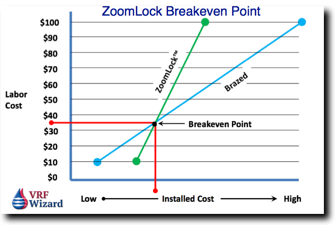
CoolMasterNet selected for a Daikin VRV System
CoolMasterNet – Daikin

After the CoolMasterNet system controller is installed it will automatically detect all the indoor VRF systems connected and their status as shown in the screen shot below. Line #1 on the screen shows that a Daikin (DK) system is installed, and on line #7 an LG System.
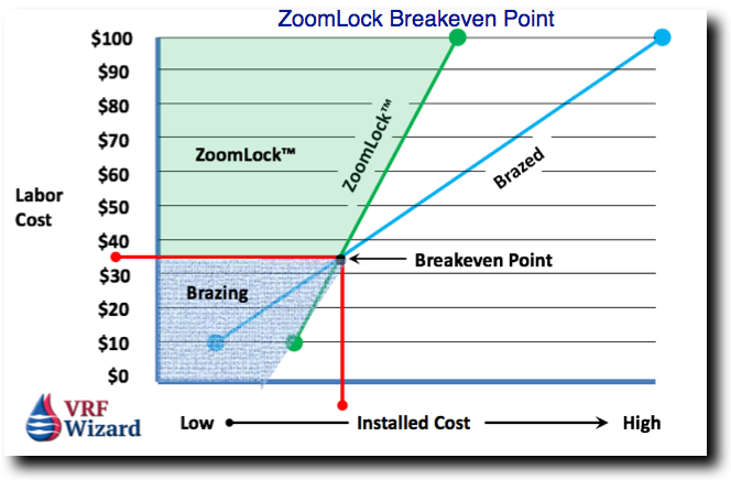
CoolMasterNet Unit Screen

The screen above allows you to scroll through all the connected indoor units while giving you the ability to toggle off any one or more of them, or all of them.

  • #1 Active HVAC line (DK 9/10)(Groups/Units)
  • #2 Inactive HVAC line.
  • #3 All ON/OFF operation button
  • #4 Scrollbar
  • #5 Connected Indoor Units with it’s address and Set-Point temperature indication.
  • #6 Indoor unit operation button (on/off)
  • #7 Service settings button
  • #8 CoolMasterNet MAC address
  • #9 CoolMasterNet IP address
  • #10 CoolRemote connectivity status

Integration with Building or Home Automation Systems

There are many options when it comes to integrating with building or home automation systems. The following integration guidelines are provided on their website; BACnet, HDL, KNX, Modbus, Rest API and Crestron Home Integration guidelines.

For BACnet there is an L3 connection to the  CoolMasterNet using a RJ45 Ethernet connector. It also interfaces using RS232, RS485, Ethernet, and KNX to connect to all major Home Automation Brands. Communicates through ASCII, MODBUS, BACnet IP, and REST API protocols.

CoolMasterNet uses industry standard wire connections.
CoolMasterNet uses Industry Standard Wiring Connections

Native cloud integration with popular smart devices, including; Google Assistant, Ecobee and Amazon Alexa, including voice controls and mobile applications.

CoolMasterNet - Native Cloud Integration
CoolMasterNet – Native Cloud Integration

Benefits

Commissioning

Commissioning can be done onsite or remotely through the CoolAutomation Service Application.

Off-Site HVAC Diagnostics and Service.

Technicians and Installers will be able to access, diagnose, and potentially solve error alerts without the need to a physical service call.

Real-Time System Error Notification

Technicians and Installers will receive error alerts for malfunctioning HVAC systems in real-time.

Adjustments

You can adjust the typical parameters like, temperature, fan speed, on/off, mode (Cooling or Heating) and louver position (angle). You can make a global change to all of the indoor units or individually. Visit their website to find out all the details: CoolMasterNet

RLS vs ZoomLock Max

0
ZoomLock Max vs RLS

On August 13, 2020, the inventor and manufacturer of the original ZoomLock fittings – RLS, LLC – announced it was ending its relationship with Parker-Hannifin and will no longer supply its fittings to Parker to sell under the ZoomLock brand. However, RLS will continue to sell the same exact fittings (sold as ZoomLock since 2015), which work with the same exact tools and jaws, under the RLS brand. RLS fittings are available at HVAC/R distributors across America and around the world.

Again, RLS fittings are EXACTLY the same as the original ZoomLock fittings…same exact product in a different box. So they work with the existing tools and jaws. Bottom line, any contractor who was using ZoomLock doesn’t need to change a thing. They just need to ask their distributor/supply house for RLS fittings. Most of the big distributors are now stocking RLS…FW Webb, United Refrigeration, Johnstone, etc.

RLS vs. ZoomLock Max Fittings

The differences are important if you consider where they product is manufactured. Especially in this current political environment where bringing manufacturing back to the USA is a campaign mantra for the two presidential candidates. RLS is manufactured in the USA, while the ZoomLock Max is made overseas.

Another important distinction is that the RLS fittings provide a wider range of sizes. The maximum size for the RLS fittings are 1-3/8”, while the ZoomLock Max is limited to 1-1/8”. Also, RLS has plans to expand their size range to include 1-5/8” and 2-1/8” fittings in the near future.

Having a long radius 90-Degree Elbow is important in ACR (Refrigerant) system to reduce pressure drop an avoid unnecessary energy consumption. The ZoomLock Max is only available in short radius 90-Degree Elbows, while the RLS 90-Degree Elbow is a long-radius elbow.

Can you use the same jaws that you have been using for the previous version of ZoomLock with the new ZoomLock Max? No, you will need to purchase new jaws as the press style is different. But don’t worry about buying new jaws as the current tools and jaws used with the previous version of ZoomLock fittings works with the RLS fittings. This is because the previous ZoomLock fittings were manufactured by RLS, so there is no need to buy anything new, just remember to buy RLS fittings, not the ZoomLock Max fittings.

Also, note that the majority of the articles written on this site about the ZoomLock fitting is no longer pertinent to ZoomLock. ZoomLock Max is now manufactured by Conex, while the previous ZoomLock fittings were manufactured by RLS. Checkout RLS/Zoomlock products on Amazon. Here is a manual pressing tool that will save you money but requires a little more muscle.

Checkout the ZoomLock vs Brazed Breakeven Calculator. (Free for downloading)

See related articles.

Reftekk Bend Designer Mobile App

0
Reftekk Bend Designer App

Reftekk provides labor savings by reducing the amount of fittings required to be brazed. If you are using the braze-free fittings, like ZoomLock, RLS, or SmartLock, you know they are expensive. With the Reftekk system there are no expensive fittings, although you’ll need to purchase the Digi-Bender machine which will pay for itself on the first significant project.

Reftekk provides a free mobile app on iOS and Android to design and accurately bend copper tubing using their Digi-Bender tool. You can easily use this app without any knowledge of the underlying CAD (computer-aided drafting) software. You can download Reftekk’s Bend Designer app from Apple’s App Store (for iOS) or the Google Play Store (for Android) on your mobile devices, just search for “Bend Designer”.

Reftekk Mobile Bending App

With the Bend Designer app and the Digi-Bender you’re not held to the standard angles of traditional fittings. If a traditional 90 or 45 degree elbow won’t work, no worries, the Digi-Bender can bend a piece of copper tubing at just about any angle the project requires, plus there is no brazing at the bends.

Reftekk Bend Designer App Steps

The first step after downloading the Reftekk Bend Designer app and agreeing to their terms

  1. Hit the “Configure Tube” button on the apps front screen.
  2. Choose the angle from 0 to 359 degrees. This is directional information only.
  3. Pick the diameter of the tubing to be bent. To the right of the diameter size will be the tool required to make the bend, which is either the Digi-Bender (5/8” to 1-3/8”) or the 370-FH hand bender tool (1/4” to 1/2”). If you have pipes run parallel to each other, start with the largest size first.
  4. Select the insulation thickness. This will help by providing insulation edge points for layout. Choices are from none to 2-1/2”.
  5. Next hit the button “+ Add Bend” to choose the angle of the first bend.
  6. Add additional bends until you have the configuration you want, then adjust the vertical and horizontal dimensions until you have the exact layout you want. There is a button that allows you to automatically choose the smallest dimension available, which is also what each dimension defaults to when it is first created.
  7. Make sure the total length shown in the upper right hand corner of the screen doesn’t exceed 19 feet, which is the maximum length of the Reftekk copper tubing.
  8. Click “Finish” when you’re ready and verify the information shown on the screen.
  9. See video below for the complete process.
Reftekk Mobile App - Adding Bends and Changing Dimensions
Reftekk Mobile App – Adding Bends and Changing Dimensions

With the mobile app you’re not restricted to just center-line reference points, you can dimension to various other points including the outside location points of the insulation. 

Editing Dimensions

You can edit most of the dimensions to create a custom fabricated length of copper tubing with various configurations and angles while still using just one piece of copper tubing. Of course, you are limited to the length of the Reftekk copper tubing available, which is currently 19 feet, but you’re eliminating many of the required brazed joints.

Easily edit dimensions in the Reftekk mobile app
Easily edit any dimension

The Digi-Bender is used with H55 rigid bendable copper tubing.

Below is a quick video (10 seconds) showing the Reftekk Digi-Bender in action.

Applications

Reftekk bendable copper can be used for plumbing, HVAC, med gas, data centers, refrigerant and VRF systems.

Reftekk was awarded the 2020 Dealer Design Award, receiving the Silver medal by ACHR News in their Contractor and Software category for the Reftekk Bend Designer app.

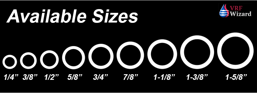
Summary

Using the Digi-Bender with Reftekk bendable copper will help eliminate up to 75% of brazed joints, thereby reducing your labor and material costs significantly.
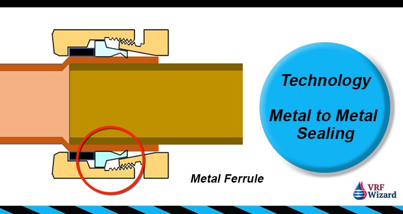
With less joints to braze there will be less leaks, less nitrogen purging and fewer warranty call-backs. With fewer brazes there is also less chance of oxidation in the tubing which can cause compressor failure.

Using the Bend Designer App from Reftekk for bending their copper tubing will increase the accuracy and simplicity of various field installation challenges by allowing precision measurements within the application. The application provides the exact locations to mark the tubing for the proper angle required and allows for multiple bends on a single piece of rigid H55 bendable copper tubing.

There are several training videos that provide for a quick start to using the Reftekk Bend Designer application for labor and material saving bends.

The Reftekk Bend Designer app is available for free in the Apple App store and the Google play store.

Here is a 19 minute video showing how easy the Reftekk mobile app is.

Resources

Reftekk Website

Reftekk YouTube Channel

Reftekk Piping Article

SmartLock Fitting

ZoomLock vs Brazed Fittings

SmartLock Fitting

0
SmartLock Fitting
SmartLock Fitting

SmartLock Fitting Review

There is another ACR fitting available that eliminates brazing in refrigerant systems called the SmartLock fitting. We will review the SmartLock fitting vs Brazed fittings in this article.

SmartLock Fitting Labor Savings

According to the manufacture the amount of time required to make a SmartLock fitting is 90% less than that of a brazed fitting. This means that the fitting only takes 10% the time required for a brazed fitting.

SmartLock Fitting saves ninety percent on labor
SmartLock Fitting saves labor

So, according to MCA, a 1/2” 90-degree elbow would take 0.40 hours or 24 minutes. This would translate into 2.4 minutes for a SmartLock fitting per the manufacture against the MCA factor of 1.0

No Flame, Fire Watch or Permit Required

One of the greatest benefits of any of compression type fittings like the SmartLock fitting is its lack of need for a flame to make the joint. The use of a flame in brazing adds to the cost due to the consumption of the gas, the need for a fire watch https://vrfwizard.com/smartlock-fitting/and the additional paperwork of obtaining a hot permit.

SmartLock Fitting No Flame Fire Watch or Hot Permit
SmartLock Fitting requires No Flame, No Fire Watch or Hot Permit

No Special Tools Required

All that is required to make the SmartLock fitting is a standard crescent wrench or a torque wrench, as opposed to ZoomLock which requires a very expensive power actuated tool. This will save you on the capital cost to get started, or at least the expense of trying out this fitting on a small project to see if it is something you feel fits into your company’s method of installing ACR tubing.

SmartLock Fitting requires no special tools
No Special Tools required for the SmartLock Fitting

No Purging or Oxidation

During the brazing process is critical to provide a continuous purge to avoid oxidation. With the SmartLock fitting there is no flame, so there is no need to purge to avoid oxidation.

SmartLock Fitting requires NO Purging

Temperature Rating

The SmartLock fitting is rated to a temperature of 302 F, which is more than adequate to meet the discharge temperature of refrigerant R410A, which is can reach up or greater than 250 F

SmartLock Fitting Temperature Rating

Available Sizes

Most of the SmartLock fittings are available in the standard sizes including 1/4”, 3/8”, 1/2”, 5/8”, 3/4” and 7/8”, with a minimum order of at least a 100 pieces for the larger sizes of 1-1/8”, 1-3/8” and 1-5/8”. I would guess that after their market share grows in the U.S. this minimum order would disappear, or that your supply house would pick up the required minimum.

SmartLock Fitting Sizes

SmartLock Fitting Technology

The highlight of the this fitting is the method by which it attaches and seals itself to the underlying tubing. The fitting uses a metal Ferrell that pinches down on the tubing to make the seal, a metal on metal seal. Most other compression type fittings use some form of elastomeric gasket that has lower thresholds of tolerance on the conditions of pressure, temperature and the copper tube condition.

SmartLock Fitting Technology

Return on Investment

There are basically three factors that determine whether the use of the SmartLock Fitting is feasible.

SmartLock Fitting Cost analysis
SmartLock Fitting Cost Analysis

These include the hourly labor rate that you pay your installers, the productivity factor of those installers, meaning how long it takes for them to braze in a fitting compared to that of the SmartLock Fitting, and lastly the material cost difference between a brazed fitting and the SmartLock fitting.

  1. Hourly Labor Rate
  2. Productivity Factor
  3. Material Cost Difference

The chart below is based on the following assumptions:

  • Based on purchasing a 1/2” 90-Degree Elbow for $3.00
  • SmartLock Fitting labor savings discounted off of a 1.0 factor of MCA for 1/2” 90-degree elbow
MEP Academy Online Courses
HVAC Sheet Metal Courses Online

To use the chart below, you would determine your hourly labor rate (#1), and then make an assumption about the percentage of labor (#2) you would save using the SmartLock Fitting, Where the intersection of the Hourly Labor Rate meets the Column based on assumed productivity is where you will find the most you should be paying (#3) for a SmartLock fitting in order to breakeven.

SmartLock fitting breakeven analysis
SmartLock Fitting Breakeven Analysis

Things to remember are that most contractors can install a 1/2” 90-degree elbow at a factor less than 1.0 of the MCA book value. This would require that the cost of the SmartLock fitting be less than the values in this chart.

Some contractors will pay more or less than the assumed $3.00 used in this example for a brazed ½” 90-degree elbow. Adjust according to your actual cost.

Warranty

The SmartLock fitting comes with a 10-year warranty, while some of the other compression type fittings limit their warranties to 5 years.

No Leakage

The SmartLock fitting claims a zero leakage rate if you follow all of their installation procedure for the proper installation of their fitting. Of course with any fitting the proper installation protocol is always required. 

This is a one-time use fittings as are most other fittings like ZoomLock. In other words, if you make a bad connection you will have to cut out the fitting and use another one.

No Flaring

There is no need to make a flare for the SmartLock fitting as it is installed on the raw cut end of a piece of tubing. 

ACR Copper or Aluminum Tubing

The SmartLock fitting can be installed on either copper or aluminum tubing without the need for any special considerations, like coated aluminum.

Summary

You will need to determine if the cost of your labor is high enough to warrant paying the premium for the SmartLock Fitting. This will be based on the three basic factors of your Hourly Labor Rate, Productivity Factor and the cost difference between a brazed fitting and the SmartLock Fitting.

There are other considerations besides cost, and that is the safety factor of using the SmartLock Fitting in settings where the use of a flame may impact other aspects of the project, such as in a senior facility where the smell of smoke may heighten anxiety for the residents or where brazing in a wood structure causes concern of a fire.

Watch the below video to see just how easy the installation of a SmartLock fitting is.

Resources

See the following related articles;

ASHRAE Study on Mechanical Piping Joints

ZoomLock vs Brazed Fittings

Reftekk Piping Solution

ZoomLock Crimping Tool Review

ZoomLock Value Calculator

ZoomLock Cost Analysis

Lokring Fitting

Visit the SmartLock website here

MEP Academy Online Courses
HVAC Sheet Metal Courses Online

VRF Heat Recovery vs VRF Heat Pumps for Homes and Commercial Properties

0
VRF for Residential Homes and Commercial Buildings

Should you install a VRF Heat Recovery or VRF Heat Pump system for a Residential home or commercial property?

We will discuss three options you have related to air-cooled split systems, not including rooftop packed heat pumps or gas/electric units.

  • Option 1 – VRF Heat Recovery
  • Option 2 – VRF Multi-Split System Heat Pump
  • Option 3 – Single Zone Split System Heat Pump

Option 1 – VRF Heat Recovery

VRF Heat Recovery Systems are mostly used for commercial buildings, so most homes are too small to reap the benefits of a heat recovery system in relationship to the added cost. If you’re going to have a lot of different zones (rooms or spaces)(#2 in image below) with different thermal requirements, and the house is large enough (think Mansion) to warrant the added cost, then heat recovery may make sense, but most likely the multi or single zone split-system heat pump system would work best as not all spaces would require conditioning at the same time.

VRF Heat Recovery System Image
VRF Heat Recovery System Diagram

VRF Heat recovery systems allows you to have some rooms in cooling mode while others are in heating mode. If you don’t believe this condition will ever exist in your home, then the Split-System Heat Pumps are the easier and more economical answer.

VRF Heat Recovery systems require some form of Branch Selector Box (#1 in image above), which provides the control mechanism that directs refrigerant flow to meet the varying demands of the Indoor Fan Coils (#2 in image). This piece of equipment is not required in a Heat Pump system. This branch selector box will need electrical power and depending on the VRF manufacture would also require a condensate drain, this adds cost to the system.

MEP Academy Online Courses
HVAC Sheet Metal Courses Online

VRF Zoning

What creates the need for simultaneous heating and cooling is the different exposures to solar loads or interior loads from lighting or plug loads (items connected to electrical outlets).

For instance if you have the sun shining through southern windows, thereby requiring cooling, while at the same time the large northern windows provide the feeling for the need to heat the space, then some form of simultaneous heating and cooling will be required.

Thermal zoning is slicing up the home or building into areas (zones) that react similar for either heating or cooling. This is usually divided according to the spaces exposure to the sun or interior loads.

Diversity

VRF Heat Recovery systems make sense when there is enough diversity in the zoning to allow for the heat that normally gets rejected to the outdoors to be used within the space, if not then there is no point in using these types of systems for energy savings.

Option 2 – VRF Multi-Split System Heat Pump

The most likely VRF system for a larger home would be the VRF Multi-Split System Heat Pump as opposed to a VRF Heat Recovery System. The VRF Multi-Split system allows you to use multiple indoor units (#5) with one or more Outdoor Units, depending  on the size of the system.

The only drawback is that you have to choose either heating or cooling for all zones, no simultaneous heating and cooling.

VRF Multi-Split System Heat Pump Diagram

System Benefits

  • Using a VRF Multi-split system heat pump allows you to have multiple indoor units connected to one outdoor unit. Each manufacture differs in the ratio of indoor units to outdoor unit.
  • You can mix the types of indoor units, such as ducted on non-ducted wall mounted units.
  • Indoor units can be of different sizes, so you can serve small or larger size rooms using the same single outdoor unit.
  • Indoor units can be of different sizes, so you can serve small or larger size rooms using the same single outdoor unit.

Option 3 – Single Zone Split System

The easiest to install and the most common residential system would be the single zone split system. This can be cooling only, or a heat pump which provides heating and cooling as required.

You can use one or more of these systems to meet the needs of your space. These can be used to handle various zoning challenges by providing one system for each zone type.

Single Zone Split System Heat Pump Diagram

Advantages and Disadvantages

  • Easiest system to install and operate.
  • Only allows one indoor fan coil unit for every outdoor unit.
  • Only allows one zone per outdoor unit.

Questions to ask yourself

  1. Do I require heating and cooling at the same time within my home or commercial property?
  2. Is my house or commercial property large enough to warrant the additional cost of a VRF Heat Recovery System?
  3. Cab I use a VRF Multi-Split System Heat Pump with the understanding that all the indoor units will be in either all heating or all cooling mode?
  4. Can I use several individual Heat Pumps to create the zoning I require?

System Comparison

The VRF Heat Recovery system has the advantage of simultaneous heating and cooling along with some energy savings based on how well the system is diversified and zoned.

The system also allows for a greater number of indoor units per outdoor unit.

It has the disadvantage of requiring additional electrical for the branch Selector Boxes that control the flow of refrigerant. This Selector boxes could also require a condensate drain depending on the VRF manufacture you use, like that of Mitsubishi.

Another disadvantage is that the system is more complex than the standard split system and requires someone knowledgeable in its installation and commissioning.

VRF System Comparison Chart

Summary

Your mechanical engineer will be able to make the decision on which system is best once they review the size and layout of your home, along with the properties elevation and solar orientation.

As mechanical engineers we understand the size range of homes can vary considerably, as we have worked on homes that were greater than 55,000 FT2, much larger than some commercial properties. These aren’t your averages homes, but they exist and are often outfitted with commercial systems, so as engineers we never say no to a system type until we have asked enough questions.

There is a very slim chance that a VRF Heat Recovery System will be specified for a home, it will most likely be a VRF Multi-Split System Heat Pump (option 2) or a Single Zone Split System (option 3), or one of the traditional methods for large structures such as chilled water and heating hot water systems.

VRF in Residential Home
VRF in Residential Homes

Have an engineer review the size, layout and orientation of your home and whether a single outdoor unit with multiple indoor fan coils would work for you, or if your home is large enough to require multiple systems.

All the split system options shown above allow for easier installations on renovation projects because of the reduced space required to run refrigerant piping in lieu of air ducts.

MEP Academy Online Courses
HVAC Sheet Metal Courses Online