


Ventilation for VRF Systems
Ventilation (outside air) can create havoc on occupant comfort if your VRF system isn’t sized or capable of handling the latent (moisture) content of the outside air. We will cover what to look for in your VRF system and what type of spaces may create a problem for ventilation air. Step 1 is to determine the latent heat of the space by following the below procedure, but first we need to understand a few helpful ratios and standards.
Moisture riding with the outside air is brought into the building to meet ventilation requirements as referenced in ASHRAE Standard 62.1. This moisture can make it uncomfortable for the occupant if the VRF system is incapable of handling excessive amounts. VRF Manufactures indicate their indoor units sensible heat ratio (SHR) which indirectly notifies you of its latent heat capabilities.

Sensible Heat Ratio
The Sensible Heat Ratio (SHR) compares the amount of sensible heat to total heat. For example if you had an Conditioner with 60,000 BTU’s of Total Heat and a SHR of 0.75, you would have 45,000 BTU of Sensible Heat Removal and 15,000 BTU’s of Latent Heat Removal (Moisture)
Sensible Heat = 45,000 BTU’s (75%) or 0.75 SHR
Latent Heat = 15,000 BTU’s (25%)
Total Heat = 60,000 BTU’s (100%)
Sensible heat is something that you can feel as it affects a change in temperature, while latent heat involves a change in state (Vapor to Liquid) in the air conditioning cycle.
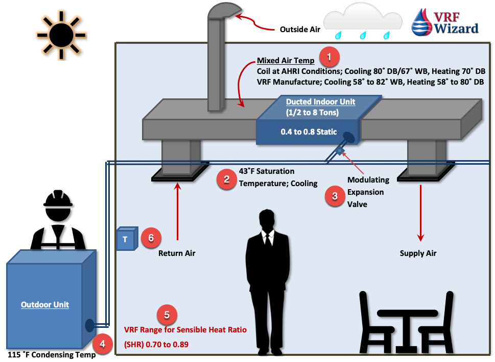
Item #1 – Mixed Air Temperature. This is a combination of the Ventilation Air (Outside Air) and Return Air. AHRI Conditions for testing uses entering air conditions of 80° DB / 67° WB at the cooling coil. VRF manufactures will show various temperature ranges, such as 58° to 82° WB in their engineering manuals allowing you to see the performance at various conditions for each of their systems.
Item #2 – 43° F Saturation Temperature
Item #3 – Modulating Expansion Valve will vary the amount of refrigerant that reaches the cooling coil in order to meet the demand of the set point of the remote controller (item #6)
Item #4 – 115° F Condensing Temperature in heating
Item #5 – VRF Manufactures will have their SHR (Sensible Heat Ratio) in the range of 0.70 to 0.89, which equates to the VRF system be able to handle 70% to 89% sensible heat and the remainder of 30% to 11% of latent heat (Moisture)
Item #6 – Remote sensor
VRF Manufactures Sensible Heat Ratio
The VRF manufactures indicate the SHR (Sensible Heat Ratio), that portion of the cooling capacity that can handle the sensible load (Temperature Difference) compared to the total load. The difference between the total capacity and the sensible is the latent heat, which is the ability of the cooling coil to remove moisture.
With VRF Manufactures sensible heat ratio’s (SHR) ranging from 0.65 to 0.89 (65% to 89%), this means that the latent capacity is equivalent to a range from 0.11 to 0.35 (11% to 35%). This requires that you check the design conditions that affect the mixed air temperature at the entrance to the cooling coil on the indoor unit. The higher the SHR, the greater the discharge air temperature will be.
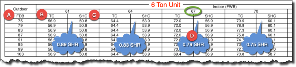
You can see in the chart below from one of the VRF Manufactures that the Sensible Heat Ratio (D) decreases as the indoor WB (Wet bulb Temperature) increases. Instead of showing the SHR, this VRF Manufacture choose to list SHC (Sensible Heat Capacity) in BTU’s. Item (C) below shows a SHC of 50.8 which is indicated in thousands, so this stands for 50,800 BTU, while item (B) TC (Total Capacity) equals 56,900 BTU. To figure the Sensible Heat Ratio from this chart, the process is the same just take the SHC/TC.
Depending on the Sensible Heat Ratio (SHR) of the VRF units you are using and the Mixed Air Temperature (return and outside air), you may need another method than the VRF indoor unit to remove the excess moisture brought in by the outside air for ventilation requirements. You need to make sure that the mixed air temperature is with the range specified by the VRF manufacture; otherwise the capacity will be diminished.
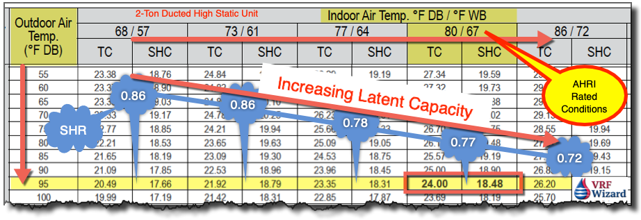
Below is another VRF manufactures 2-Ton Ducted High Static Indoor Unit. As the indoor air temperature increases the Sensible Heat Ratio decreases, while the Latent Heat capacity increases. Increasing latent capacity comes at a sacrifice to an increase in the indoor temperature. This VRF manufactures 2-Ton ducted indoor unit at AHRI Standard 1230 conditions is rated at 24,000 BTUH at an indoor Entering Air Temperature of 80° F DB / 67°F WB based on an outside air temperature of 95°F DB/ 75°F WB
18,480 BTUH Sensible / 24,000 BTUH Total = 77% Sensible (23% or 5,520 BTUH Latent)
High Occupant Spaces and VRF
The higher the occupant load of the space, the more ventilation air required to meet ASHRAE standard 62.1 or if you live in California, then you would need to meet Title 24 of the energy code.
High density occupant spaces can put a latent burden on your VRF system. Depending on the SHR of the VRF unit as shown above in the example VRF chart there are limits to how much moisture or latent heat a VRF system can handle. According to ASHRAE standard 62.1 there is a requirement to bring in the minimum amount of ventilation (outside air) for each occupant of a space. The more occupants, the more outside air and its constituents of sensible and latent heat.
ASHRAE 62.1
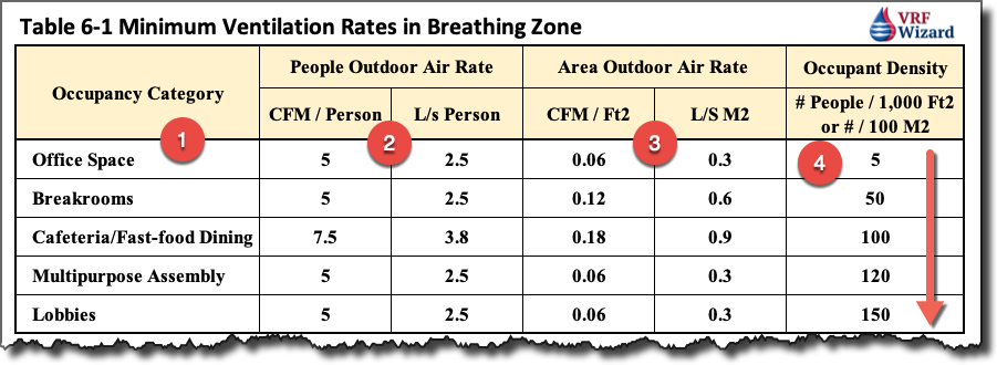
The above Table 6-1 is a replication of the ASHRAE Standard 62.1. To understand how engineers determine how many occupants are required per space type there are various sources that can be used based on the local code authority, but for this simple example we’ll use the above table.
Occupancy Category defines the space type that is under consideration for determining the ventilation requirements. In column #1 above we have listed just a few of the hundreds of occupancy categories listed in ASHRAE’s table 6-1
Occupancy Density (Column #4) defines how many people are to be considered to occupy the space for every 1,000 Ft2 or people per every 100 M2. If you have a 500 FT2 office space, then the following quantity of people would be required according to the calculation as such; 600 Ft2 / (5 people/ 1,000 Ft2) = 3 People

People Outdoor Air Rate (Column #2) defines how much CFM (Cubic Feet per Minute) that must be provided for every person determined by the occupant density requirements.
Area Outdoor Air Rate (Column #3) defines the additional CFM/Ft2 required for the off-gassing and other contaminants generated by the space and its furnishings.
Example Ventilation Requirement
500 Ft2 Breakroom
Step 1 – Figure total Occupant Density (500 Ft2 / (50 people / 1,000 Ft2) = 25 People
Step 2 – Multiple People by column #1 (CFM/Person) to get total CFM for Outdoor Air (25 People x 5 CFM/ Person) = 125 CFM
Step #3 – Figure the CFM required for column #3 (Area Outdoor Rate). 500 Ft2 x 0.12 CFM / Ft2 = 60 CFM
Step #4 – Add the two values together (125 CFM + 60 CFM = 185 CFM)
How do you get from CFM of ventilation air to latent heat in BTUH. The simple answer is by using the following calculation, which would require a psychometric chart or computer program.
2019 Building Energy Efficiency Standards Title-24
If you live in California, then you will go by section 120.1 of Title 24, which provides for the requirements on ventilation. Section 120.1(b) is for High-rise residential Buildings, but we will cover section 120.1(c)3 which covers Nonresidential and Hotel/Motel Buildings using a mechanical system, as opposed to natural ventilation.
The system needs to be designed to meet one of the two following methods whichever provides the larger outdoor flow rate (CFM).
Method 1
(Equation 120.1-F) Vz = Ra x Az
Where:
Ra = Outdoor airflow rate required per unit area as determined from Table 120.1-A
Az = Zone floor area is the net occupiable floor area of the ventilation zone in square feet.
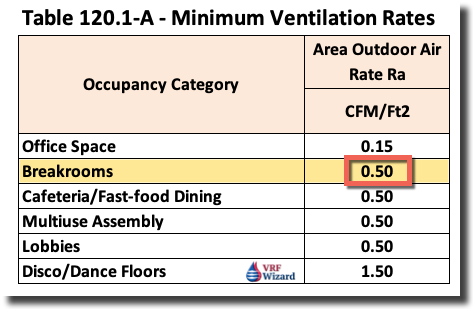
Method 1 Example (Breakroom Space)
Ventilation CFM = Air Rate (from table 120.1-A) x Square Footage of Breakroom (1,000 Ft2)
Ventilation CFM = 0.50 x 1,000 = 500 CFM
Method 2
This method uses a calculation based on a fixed amount of occupants or fixed seating. This can be based on the engineers design occupant quantity or fixed seating quantity. California Building Code table 1004.1.2 “Maximum Floor Area Allowances per Occupant,” indicates occupancy parameters based on room types.
(Equation 120.1-F) Vz = Rp x Pz
Where:
Rp = 15 cubic feet per minute of outdoor airflow per person
Az = The expected number of occupants. The expected number of occupants shall be the expected number specified by the building designer. For spaces with fixed seating, the expected number of occupants shall be determined in accordance with the California Building Code.
Converting Latent Heat CFM to BTUH
Latent Heat BTUH = CFM x 0.68 x Delta-Grains (Outdoor Grains – Indoor Grains) See our YouTube video explaining this calculation using a psychometric chart.
Other Latent Heat Loads
In addition to the ventilation air (outside air) adding latent heat (moisture) to the space, there are other contributing factors. People give off sensible and latent heat. People give off about 140 BTUH when they are seated at rest. Equipment and infiltration can also add moisture to the space.
Ventilation – People – Equipment – Infiltration
So what do you do if your VRF system can’t manage all the latent heat coming into the system from ventilation air, people, equipment and infiltration? There are several options that we have already covered in other articles that you can find links to within this article.
The solution is to provide another means of removing the latent heat (Moisture) and not rely on the cooling coil of the VRF system.
DOAS – Dedicated Outside Air Systems
One of the options available for handling the excessive moisture that the VRF system is incapable of removing is to use a DOAS system. The DOAS system can handle the additional moisture that the VRF system isn’t size to remove, plus it provides additional static pressure and airflow. See this article on DOAS systems or VRF Ventilation Alternate Systems
Summary
ASHRAE Standard 62.1, “Ventilation for Acceptable Indoor Air Quality,” under the mechanical ventilation method needs to be carefully reviewed when designing a VRF system to ensure that there is sufficient capacity to handle the moisture brought into the space for ventilation (Outside Air). Ducted VRF systems have limited capacity to handle moisture. Check the SHR (Sensible Heat Ratio) of the indoor VRF unit and the fans static pressure rating to determine if they are sufficient to meet the requirements of the space.
Identify the space type where the VRF system is being proposed and calculate the latent heat from the ventilation, infiltration, occupants and any equipment giving off moisture. Select a VRF System that can handle the latent load if possible, if not, then select an alternate method of conditioning the ventilation air before it hits the VRF cooling coil.
Resource Links
How to Calculate Cooling Coil Heat Transfer


 effect the ability of the VRF system to handle the Latent Heat (Moisture)? Sensible and Latent Heat capabilities of VRF.)