Home Blog Page 4

Energy Meters – Billing Tenants for AC

0
energy metering of tenant spaces

Tenant Submetering

How do you bill tenants for their share of the use of a piece of air conditioning equipment that is shared amongst more than one tenant in your building? If you have a VRF Air Conditioning system, where one or more Outdoor Units feed multiple tenant Indoor Units, then you have an opportunity to bill each tenant according to their usage. The more they use, the more they pay for the energy consumed to run their VRF air conditioner.

Energy Meter

By using an energy meter that’s connected to the power source feeding the outdoor air conditioning unit, you will be able to allocate the operating cost of those units. An energy meter uses CT’s to record various electrical consumption data for use in the cost allocation formula. The energy meter can provide information on kWh, kW, PF, kVAR, Volts and amperes.

Power Proportional Distribution (PPD)

Daikin has what they call a Power Proportional Distribution (PPD) option for their VRV system. The PPD software allows owners of multiple tenant buildings, to charge those tenants based on an allocated amount of power used by the Outdoor portion of the VRV air conditioning system. The energy meter sends a pulse to the iTouch Manager Control panel which with the optional PPD determines how much each tenant is using their air conditioning system. The factors that go into the calculation include information coming from the tenant’s indoor unit.

How it’s Done
Energy Meter Billing Tenant fo AC
Energy Meter Connected to VRF Controller and Power to ODU

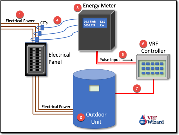
The Energy Meter (#3) is connected by CT’s (#4) to the electrical Power (#1) feeding the Outdoor Unit (#2). The Energy Meter (#3) provides a Pulse Input (#5) to the VRF Controller (#6). The VRF Controller contains the PPD option that according to Daikin;

“Mathematically calculates each indoor unit’s portion of that outdoor units total power consumption based upon its return air temperature, electronic valve position and baseline values determined by the factory. PPD is compatible with Daikin VRV 2-pipe Heat Pump technology and VRV 3-pipe Heat Recovery technology.”

The math in the formula is using the most predictive elements of the indoor system to allocate energy used by the outdoor unit to support the indoor unit’s requirements. Basically it looks like this;

Power Consumption of Outdoor Units / Tenants = Charge per Tenant

As you can see it appears very simple, but there are some things you need to get right when installing one of these systems.

  • You need to make sure that you are able to isolate the outdoor unit’s electrical wires from other electrical loads. The CT’s (#4) need to capture just the electrical feeding the Outdoor Units (#2) which feed the indoor units you want to charge for energy usage.
  • You need to select the Energy Meter (#3) that meets the electrical requirements of your Outdoor Units (#2). The correct voltage, amps and phase needs to match your electrical system requirements.

The Intelligent Manager III with the PPD software option is designed, engineered and commissioned by Daikin for each project. Internal PPD results are temporarily stored within the Intelligent Manager III IPU’s for up to 2 days and subsequently written to the PC hard drive for permanent storage.

Daikin’s Intelligent Touch Controller can accommodate up to 3 pulse inputs, and up to 6 with the addition of the DIII-Net Plus Adapter. The internal PPD software results are stored within the Intelligent Touch Controller for up to 12 months.

Data Output

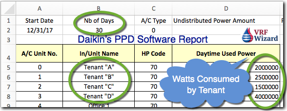
The PPD software will output data in Excel using the .csv file format (comma separated values) identifying the individual indoor units and the power that they have consumed over a certain period of time. The problem is how you get all this information into your accounting system or into a billable format for your tenants. This is where you will need to work with your contractor to create something that makes sense for your company and how you want to see and present the data.
Daikin PPD Software Report

You can retrieve the data remotely through your web browser or through a memory slot in the iTouch Controller or through a PC for the Intelligent Manager III. You can run the report for a range of days or for the whole month. The PPD software reports will breakdown the power used by indoor fan coil, which should relate to the tenant spaces. You can use the Excel .csv file to quickly calculate what each tenant owes.
Daikin PPD Energy Metering

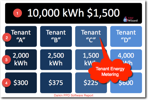
From the Daikin PPD Software report we can get the information required to allocate the electrical bill to each of the tenants in proportion to their usage. This is fair to everyone. In our example, the total usage and charges for the whole building was 10,000 kWh and $1,500. We can now use our Daikin PPD Software report to charge the tenants for their share as follows

  • Tenant “A” used 2,000 kWh for the month. 2,000/10,000 = 20% * $1,500 = $300
  • Tenant “B” used 2,500 kWh. 2,500/10,000 = 25% * $1,500 = $375
  • Tenant “C” used 1,500 kWh. 1,500/10,000 = 15% * $1,500 = $225
  • Tenant “D” used 4,000 kWh. 4,000/10,000 = 40% * $1,500 = $600

Which Energy Meter to Use

There are many manufactures of Energy Meters, but currently there are only two recommended by Daikin if you are using their system.

Indoor Unit Energy Meter

It’s also possible to meter the energy consumed by the indoor units if this option is desired. This will add considerable cost and time to the project. Each tenant would need an Energy Meter on the electrical power lines feeding the indoor units. The energy meters would need to capture the power feeding the indoor units exclusively. It’s better to rely on the PPD software to make the calculations of usage based on its internal algorithm.

Installation and Administrative Billing

There are several options when it comes to having an Energy Meter installed. Your HVAC Service contractor or Building Automation contractor can install the meter and provide the data needed for billing the tenants. The property management firm then can use that information to charge the tenants.

If you have in-house facility management personnel, then they could possibly install the meters and provide the required information to the property management company or to administrators for billing.

There is a minimum amount of training required to read the data, so anyone can learn what to look for and how to decipher what’s needed.

Summary

If you want to charge your tenants for the energy they consume running their VRF/VRV Heat Pump or Heat Recovery systems, then using Energy Meters as described in this article is probably the easiest solution with the quickest payback. Know what you are going to do with the data before purchasing and setting up an energy meter for billing tenants. Submetering of the indoor units is not necessary as the PPD software allocates this cost based on the data it collects about the tenant’s usage of the indoor unit.


Subscribe to our mailing list

* indicates required


MEP Academy Online Courses
HVAC Sheet Metal Courses Online

VRF Piping Layout

0
VRF Piping Layout

Manufactures VRF Piping Layout Drawings

The VRF Piping Layout is highly engineered by the VRF manufactures software to design the pipe sizes to meet the capacities and conditions required, including ASHRAE 15. The pipe sizes are affected by capacity, pipe lengths and the quantity of fittings. When any of those factors change than the design engineer needs to enter the new parameters into the piping design software to recalculate the new requirements. The changes could affect the sizes of the pipes required and the refrigerant charge.

VRF Piping Design Software
VRF Piping Design Parameters

When Should You Recalculate

When doing a VRF project the installing contractor is most likely working off of either a designed floor plan without sizes shown, in which case the piping schematics provided by the VRF manufactures software program are used for the correct pipe size. The VRF manufactures piping schematic is based on the capacity, design piping lengths and quantity of fittings. If any of these factors change then the calculation for pipe size must be recalculated using the VRF Manufactures software program.

If you have a VRF piping layout (schematic) showing that you have a 1-ton indoor unit that requires a 1/4” (6.35mm) liquid line and a 1/2” (12.7mm) gas line based on the pipe length being 20 feet (6 meters) from the branch selector box with 2 elbows, but due to field conditions you actually have 40 feet (12.19 m) of pipe and 6 elbows, then you will need to give this information to the design engineer to put into the VRF manufactures software to recalculate the required pipe size. It’s possible that no increase in size will be required, but if it is required, and you don’t make the change, you will reduce the capacity of the indoor unit.
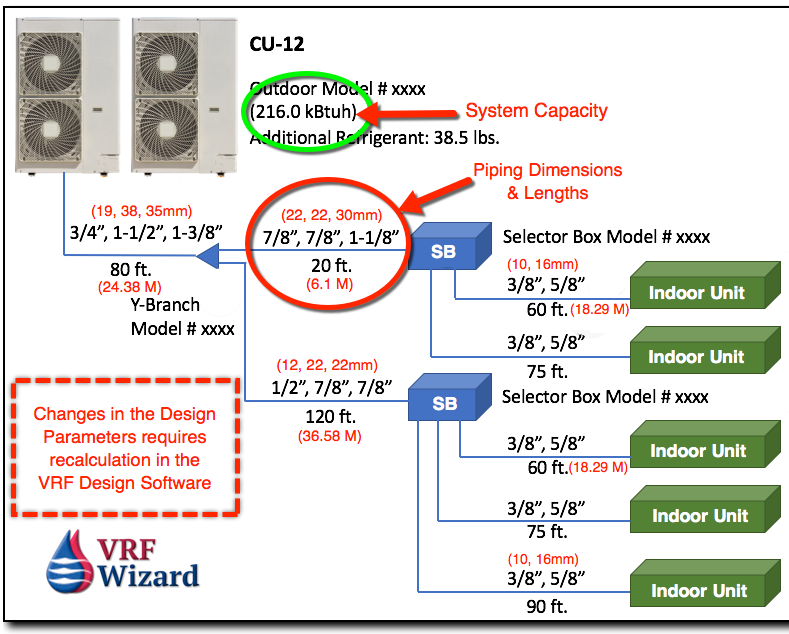
The installing piping crew must follow the VRF manufactures piping schematic and provide any changes to the design engineer before installation begins. Not only do additional lengths of pipe impact the pipe size, but the total refrigerant charge required. The amount of refrigerant in a VRF system is critical to a successful system, so any changes to lengths is very important. The actual length to be installed is the only accurate method of getting the proper refrigerant charging amount.

Of course, you need to make these changes before installing any of the piping in case changes are warranted.

You might have noticed that we have mention multiple times the need to recalculate if there are any changes, that’s due to the importance of this in VRF System Design and installation.

Full Port Refrigerant Ball Valves

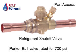
Using full port refrigerant ball valves with Schrader ports allows for isolation of any indoor unit without having to shut down and drain the complete refrigerant from the system. Make sure to check with the design engineer for the approved location of the ball valves in accordance with the VRF manufactures design guidelines.


ball valve for vrf refrigerant system
Parker Refrigeration Isolation Ball Valve with guage port

Refrigerant Piping Supports & Seismic

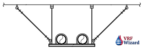
Consideration must be made for how you will support long runs of piping inside the building or outside on the roof or up a shaft, etc. Will you use a B-Line Dura-Blok for piping supported on the roof as shown below? Will you use single point hangers or a trapeze?

Do you live in an area known for earthquakes? Do you need to comply with seismic restraint requirements? If so, you might need something similar to this detail. SMACNA provides guidelines on the installation of seismic restraints. The piping below is shown supported on unistrut rack, with vibration isolation springs and seismic cables.

Pipe Seismic
Pipe Seismic

Expansion Loops

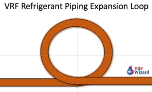
Review our article on the use of expansion loops for long piping runs to avoid pipe ruptures due to expansion. Check with the design engineer for this requirement on your project.

VRF Refrigerant System Piping Expansion Loop

VRF Startup & Commissioning

The VRF system price often includes a Factory representative to assist with the startup and commissioning of the system. This individual will want to ensure that the system has the appropriate refrigerant charge.

It’s important not to energize the power to any of the equipment before the piping is installed if you are using a nitrogen purge with brazing. Energizing the equipment could cause the EEV’s to close, preventing the nitrogen purge from doing its job.

VRF Piping Fitting Types

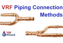
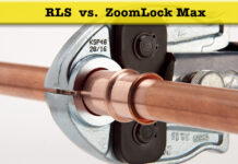
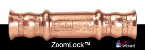
There are many ways to make a piping connection, including Brazing, flaring and pressfit. Checkout our article on the ZoomLock fitting versus Brazing and our ZoomLock Cost Analyses,, Reftekk Piping Solution, and LokRing Fittings

ZoomLock coupling
ZoomLock coupling

Special VRF Piping Requirements

  1. Use dedicated R410A refrigerant hoses
  2. Dedicated R410A flaring tool. Flares are deeper due to increased operating pressure.
  3. All pipes get insulated.
  4. Y-Branch when installed horizontally. LG allows a +/- 10 degree rotation from the horizontal plane, Daikin allows up to +/- 30 degrees.
  5. Confirm minimum distances between fittings. LG is 20” (508mm)
  6. Avoid creating oil traps. If required use inverted trap within VRF manufactures guidelines.
  7. Headers have to have homeruns to Indoor Units, without other Y-Branches or Headers in-between.
  8. Use a torque wrench for proper tightening of flared fittings to prevent leaks.
  9. Use dry nitrogen purge when brazing.
  10. Use expansion loops for long runs of piping.
  11. Minimize piping lengths and fittings.
  12. Report back to the Design Engineer any changes in the system installation.

Checkout Job Walk Basics 101 – What you need to know when attending a job walk on a retrofit project.

Subscribe to our mailing list

* indicates required


MEP Academy Online Courses
HVAC Sheet Metal Courses Online

VRF Piping Design Software

0
VRF Manufactures Piping Layout Software

VRF / VRV manufactures require that you use their proprietary software to design the refrigeration piping for the installation of their VRF systems. You or your engineer will need to have a cooling and heating load to import or use with the VRF piping design software. Using energy modeling software is great for Heat Recovery Systems and optimizing zoning layout. Below you will find a list of links to each of the Manufactures free VRF Piping Design Software. Here is what you can expect to receive.

VRF Piping Diagram

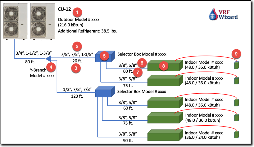
The VRF manufactures software will provide a schematic piping diagram showing all the outdoor & indoor units along with any accessories. The schematic piping diagram will also show the pipe sizes and lengths that were used in the calculation. There will also be model numbers for the equipment and accessories with the schematic. All fittings and valves are converted to an equivalent length of pipe when calculating piping and system size.

Of course you will be asked to enter the lengths of piping unless your VRF sales representative has agreed to do it for you based on a set of plans and specifications. The software will automatically indicate whether the design has exceeded the allowable lengths as dictated by the VRF manufacture.

VRF Piping Layout Software

The VRF Piping Design Software should give you the following as shown in the Piping Diagram above;

  1. Model # and Size of the Outdoor Unit
  2. Pipe Sizing from outdoor Unit to Branch Selector or Indoor Unit
  3. Pipe Lengths for each section
  4. Model numbers of all “Y”-Branch Fittings and where they are located.
  5. Model # of all Branch Selector Boxes
  6. Pipe Sizing from Branch Selector Boxes to Indoor unit
  7. Pipe Lengths for each section
  8. Model # of all Indoor Units and its Cooling & Heating Capacity
  9. Thermostat or controller Model #

Looking at the above VRF piping diagram you can see everything is drawn with a single line, but that there are three dimension (3-Pipe System) for the pipes leaving the Outdoor Unit, and two dimensions (2-Pipes) leaving the branch Selector Box going to the Indoor unit. This makes the drawing is easier to read.

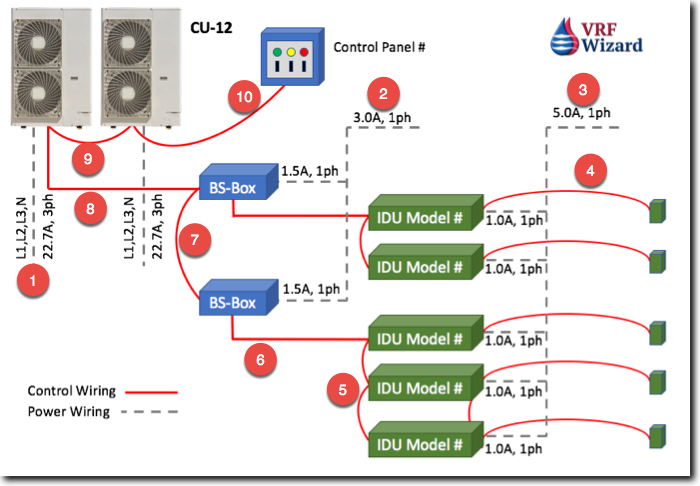
VRF Electrical & Control Wiring Diagram

The VRF manufactures will provide a schematic of the electrical and control wiring diagrams showing how all of the components of the system are powered and controlled. The schematic will indicate the power and control wiring size and type.

VRV Control Wiring
VRV Control Wiring

The VRV Design Software should give you the following as shown in the Wiring Diagram above;

  1. Power Wiring for Outdoor units
  2. Power Wiring for Branch Selector Boxes
  3. Power Wiring for Indoor Units
  4. Control Wiring from Controller to Indoor Units
  5. Control Wiring between Indoor Units
  6. Control Wiring from Indoor Units to Branch Selector Box
  7. Control Wiring between Branch Selector Boxes
  8. Control Wiring between Branch Selector Boxes and Outdoor Units
  9. Control Wiring between Outdoor Units
  10. Control Wiring to Main Controller if used.

Bill of Materials

The VRF Piping Design Software will provide a bill of materials for the project which should include the following at a minimum;

  • Equipment Model Numbers & Capacity
  • Accessories: Branch Selector Boxes, Y-Branches, Headers, etc.
  • Piping sizes and lengths
  • Controls, thermostats
  • Factory refrigerant charge & additional refrigerant charge required

Equipment Schedules

The VRF/VRV Design software will generate equipment schedules that can be used on your CAD design drawings. This will save you time and money from not having to make this yourself.

Refrigerant Charge

The software will generate an estimated quantity of refrigerant that you will be required to supply to meet the required capacity of the system. The outdoor unit should come pre-charged with an amount for the system excluding the piping. The amount of refrigerant charge should be indicated in the report.

VRF System Sizing Diversity Factor

This is known by the various names that each VRF manufacture uses to describe the ratio of Indoor Unit Capacity to Outdoor Unit Capacity. There are two formulas often used to express system/load diversity. The first involves the total peak load of all the indoor units divided by the total capacity of the outdoor units that they’re connected to.

Indoor Unit Capacity (Btuh) Total of Peak Loads / Outdoor Unit Capacity (Btuh) = Diversity Ratio.

Cooling Load diversity occurs when the engineer provides zoning of the indoor units with different peak load times. Outdoor units serving a block load contains zones that peak on different days at different times, allowing for the outdoor unit to be smaller than the sum of the peak loads of each indoor unit. This is often achieved by combining zones with different solar exposures onto the same outdoor unit. The second formula involves the total Block Load divided by the Total Capacity of the Outdoor units.
Block Load Capacity / Total Outdoor Unit Capacity = Building Load Diversity

VRF Piping Design Software Links

Unfortunately some of the VRF manufactures have several divisions throughout the globe with differing links and names for their software. Here are a few.

LG – LATS Multi V
Daikin – VRV Web Xpress
Mitsubishi – Diamond System Builder
Samsung – DVM Pro
Carrier – VRF Software
Toshiba (UK) – DesignAirs
Hitachi – HI-Tool Kit 

What you will need to get started

  1. Heating & Cooling Loads with zoning requirements.
  2. General layout of equipment components in building.
  3. Lengths of piping between pieces of equipment
  4. Type of Ventilation system
  5. Type of Indoor Units for each space.

The VRF Manufactures representative will often provide the above information free of charge with the hopes that they will be able to sell you the equipment and accessories. Contact your local VRF/VRV supplier for information on the above VRF Piping Design Software.

Subscribe to our mailing list

* indicates required


MEP Academy Online Courses
HVAC Sheet Metal Courses Online

VRF Installation with Mighty Bracket

0
mighty bracket

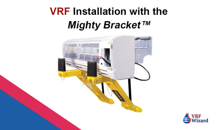
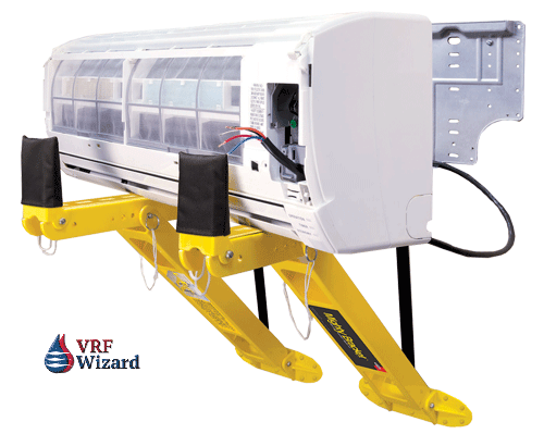
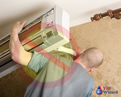
The Mighty Bracket™ makes installations of wall mounted air conditioners capable of being done by one person safely. No need for someone to hold the wall mounted A/C unit like this guy below, while you make the piping or wiring connections, freeing your hands to do the necessary work.

Mighty Bracket Easy Install
Avoid what he is doing, and get the Mighty Bracket™ for easier installs.

Doing VRF Mini-split system installations with the Mighty Bracket™ will save you time and money. Not only will you save money, but the Mighty Bracket will increase the safety of installations, as you won’t need to support the wall mounted air conditioner with your hands as you work.

Mighty Bracket Rectorseal

Features:

  • Allows single person installation
  • Simple clip on support
  • Doesn’t damage walls
  • Used on most brands of Mini-Splits
  • Folds for easy storage
  • Inclodes tote bag

Note: When installing the indoor unit’s mounting plate, ensure that the correct hardware is used. If hung on drywall, it is recommended to attach the plate to a stud, making certain that the tab area is securely attached to the wall. Add more screws around mounting plate tabs for heavy units. Always install mounting plate according to the manufacturer’ published instructions. Get the Mighty Bracket today and save on straining.

Warning: Bracket not to be used for weight above 100 pounds.

The Mighty Bracket


The Mighty Bracket™ is a trademark of RectorSeal®

Subscribe to our mailing list

* indicates required


VRF Advantages

0
VRF VRV Advantages

VRF Advantages

      1. Heat Recovery units can utilize heat removed from zones providing cooling to heating zones requiring heat.
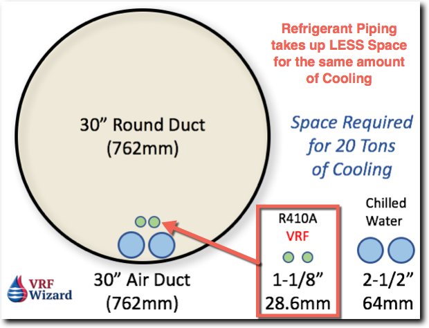
      2. VRF systems take up less room than other system types, freeing up valuable mechanical room space for other purposes.
      3. Reduced usage of ductwork and the space required for moving air around the building.VRF Advantages - Space Requirements
      4. Historical buildings with limited space for air ducts and to minimize disruption of architectural features.
      5. In commercial retrofit projects, it’s possible that all the VRF equipment can be brought into the building with use of the elevators, avoiding costly cranes or rigging.
      6. Increase in energy efficiency with the elimination of large supply air fans. Requirement for DOAS may negate some of this advantage, but OSA ventilation will require smaller ducts and fans.
      7. Smaller and lighter equipment on the roof can mean less structural requirements than other system types.
      8. Using VRF in new construction reduces the need for large air ducts allowing for the possible reduction in building height.
      9. Quiet operation of the VRF indoor units and Outdoor units.
      10. Possible LEED® points for energy efficiency.
      11. Variable speed compressors for increased efficiency at part load.
      12. If using more than one outdoor unit twinned together, one can be down for maintenance while the other is still running.
      13. Modular design allows for easier expansion.
      14. Lighter roof mounted equipment than conventional HVAC equipment requires a smaller crane, thereby reducing rigging cost.
      15. Using a VRF Heat Recovery System avoids having to have two separate system and pieces of equipment to maintain, a Chiller for chilled water and a Boiler for heating hot water.

    Please email us other VRF advantages of using this technology on projects that can be added to this list.

    Subscribe to our mailing list

    * indicates required


Lokring Fitting

0
lokring tool and fitting

The LOKRING fitting is a Pressfit fitting used for many applications within many industries. We will be looking at the LOKRING for its potential use with refrigerants in the VRF/VRV industry.

(Click here to Enlarge Lokring Infographic)

Lokring fitting infographic

Share this Image On Your Site

US Coast Guard Approved

The LOKRING tube connectors have been approved for use by the US Coast Guard to repair the refrigeration and air conditioning systems on the Coast Guard vessels. The LOKRING fitting meets military standards MILSTD-777.

If it meets the US Coast Guards standard for the repair of their refrigeration and air conditioning systems aboard their vessels, then you might trust it in your project.

Lokring claims the following air conditioning manufactures as users of their LOKRING fitting, Hitachi, Samsung, LG & Mitsubishi.

Lokring Fitting Labor Savings

The Lokring Fitting claims a 40% Labor savings with the same benefits as other Pressfit type joints. There is no Flame, Fire Watch or Burn permit required, no nitrogen purge and the benefit of using non-skilled workers.

There are three pieces to make a joint.

  • Joint Qty=1
  • LOKRING Qty=2
  • Stabilization Qty=2

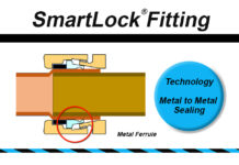
Compare this to the ZoomLock fitting which only requires one piece to make a Pressfit joint. Also, the ZoomLock Fitting claims a 60% or greater savings on their joining system, and the SmartLock fitting which claims a 90% savings over brazed fittings. There is another piping connection system called RefTekk that claims to reduce brazed connections by up to 75%..

Temperature Range -58F up to 302F (-50C up to 150C)

Lokring Fitting Size Range

1/4” to 1-3/8” (6 to 35mm) 1/4”, 5/16”, 3/8”, 1/2”, 5/8”, 3/4”, 7/8”, 1”, 1-1/8”, 1-3/8” (6mm, 6.35mm, 8mm, 9.53mm, 10mm, 12mm, 12.7mm, 15mm, 16mm, 18mm, 19mm, 22mm, 25.4mm, 28mm, 28.6mm, 35mm)

Lokring Fittings Available

Straight Brass Connectors (Couplings), 90 Elbows, 45 Elbows, Reducers, Tee’s, Reducing Adapters, Connector with Schrader Valve, Euro Flare Fitting, YP Branches, T-Branches, Headers, Stoppers (End Caps), Ball Valves with Schrader Valves

Also available are Heat Shrink Sleeves with Hotmelt Adhesive for corrosive environments, such as experienced by the US Coast Guard vessels.

Maximum Operating Pressure 1,088 psi (75 bar)

Checkout ASHRAE’s Study on Mechanical Piping Joints

The direct competitor of Lokring is ZoomLock or SmartLock which are covered in the following articles;

  1. ZoomLock Cost Analysis 
  2. SmartLock Fitting
  3. ZoomLock Value Calculator Review
  4. ZoomLock vs Brazed Fittings
  5. ZoomLock Klauke 19 kn Tool Review
  6. Reftekk Piping Solution

Video of the LOKRING by Vulkan

Website: LokRing Website
Installation Instructions (English): LokRing Installation Manual

LOKRING™ is a Trademark of Vulkan

Subscribe to our mailing list

* indicates required


Calculating Cooling Load

0
Calculating Cooling Loads

Calculating Cooling Load

What exactly determines the size of the heating and air conditioning system and the required amount of air (CFM) to be delivered to the space? in this article we’ll show you what goes into calculating the cooling load of a building and the CFM for a typical exterior room with a window.

(Click here to enlarge Infographic)

calculating cooling loads vrv

Share this Image On Your Site

Sensible Heat Equation

The following are the formulas you can use to determine the requirements for any room. You will first need to determine the total heat gain for your space as shown below.

Btuh = CFM x 1.08 x (EAT – LAT)

CFM = Btuh / 1.08 x (EAT – LAT)

EAT = Indoor Design Temp (DB)
LAT = Supply Air Design Temp

Sensible Heat is a Change in Temperature (DB) with no change in moisture content.

There are 4 Main Contributors, and several others that contribute to Sensible Heat gain based on variables that we will discuss later.

1) People – Internal Sensible Load

ASHRAE Sensible Load per Person

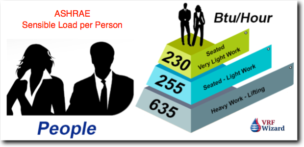
People add heat to the space they occupy. The amount of heat they contribute depends on the level of activity they are involved in. ASHRAE show various levels of activity, such as “Seated – Very Light Work (230 Btu/Hr), Seated – Light Work (255 Btu/Hr) and Heavy Work – Lifting (635 Btu/Hr)”.

As the level of activity increases, so does the amount of heat that a person gives off to the space they occupy and the more air conditioning capacity you will need. A gym needs more air (CFM) per square foot or meter than does an office space of the same size.

Sensible Heat from People

ASHRAE – Occupancy Heat Gains

Seated, Very Light Work ……………. 230 Btu/hour

Seated, Light Work ………………….. 255 Btu/Hour

Heavy Work, Lifting …………………. 635 Btu/Hour


2) Lighting – Internal Sensible Load

Lighting Sensible Heat Load

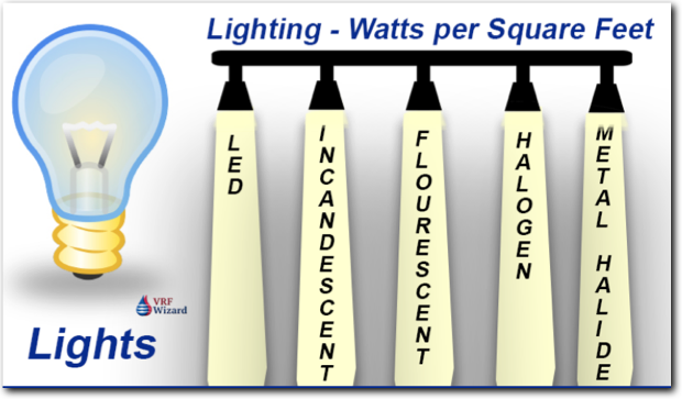
Lights give off heat in various quantities based on their properties. Incandescent are the least efficient and turn a lot of their energy into heat instead of light. The more efficient LED that are commonly used in lighting retrofits and put off less heat for the same amount of light as other types. You will need to know the total watts of the lights in the space you are calculating your heat load for. For most commercial spaces you can assume 1 watt per square foot or less. (10.76 Watts/M2)

Each Watt is equal to 3.41 Btu’s, so the more watts you have the more heat added to the space and the larger the air conditioner gets.

Sensible Heat from Lights

1 watt = 3.41 BTU

Q = 3.41 Btu/Watts x Watts

200 Watts x 3.41 Btu/Watt = 682 Btu/Hour

Excludes lighting use factors & ballast allowances. Assumes CLF = 1


3) Plug Loads – Internal Sensible Load

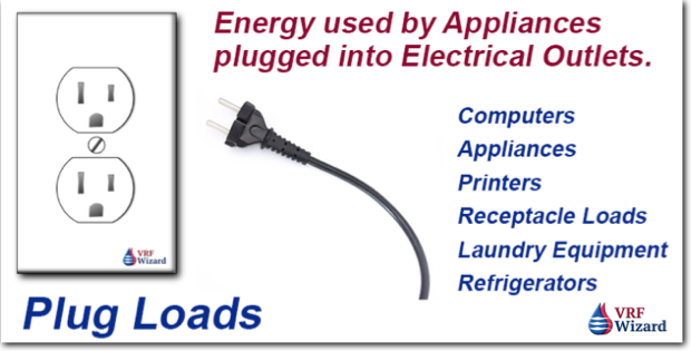
Computers, Appliances and Equipment that are plugged into electrical outlets.

Plug Loads - Sensible Heat Gain
Plug Loads – Sensible Heat Gain

Plug loads account for everything plugged into an electrical outlet. This can be accounted for by using an assumption of 1 watt/Ft2 or less as discussed in this ASHRAE article on Plug Loads.

Sensible Heat from Plug Loads

1 watt = 3.41 BTU

Q = 3.41 Btu/Watts x Watts

150 Watts x 3.41 Btu/Watt = 512 Btu/Hour


4) Solar Loads – External Sensible Load

Solar Load - External Sensible Load
Solar Load – External Sensible Load

Conductance – Wall & Glass

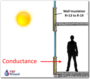
The solar load is composed of sensible heat gain due to conductance and radiation.

Solar or the external design temperature has a large effect on the internal heat gain when calculating cooling loads for sizing air conditioners. Heat is gained through the building construction based on the surface area, resistance of the materials and temperature difference between the design outdoor and indoor temperatures per the following formula.

Solar Load through Glass by Conductance

solar load by conductance

Q = U x A x TD

Q = Btu/Hour

U = The U-Factor is the reciprocal of the Resistance

A = Area (Ft2) of Building Component

TD = Temperature Difference

Solar Load through Wall Construction by Conductance

Solar Gain - Conductance thru Wall
Solar Gain – Conductance thru Wall

Solar Radiation – Glass

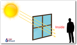
Glass exposed to the suns rays will allow heat into the building based on the Area (Ft2) of the window, the SC (Shading Coefficient) and its SCL (Solar Cooling Load Factor)

Solar Load through Glass by Radiation

Solar Load by Radiation

Q = A x SC x SCL

Q = Btu/Hour

A = Glass Area (Ft2)

SC = Glass Shading Coefficient (Effected by window blinds)

SCL = Solar Cooling Load Factor

Shading Coefficient is a ratio from comparing the proposed glass to a benchmark plain glass.

Solar Cooling Load Factor is based on glass orientation, month, time of day & geographical location.


How to Calculate Total Sensible Load

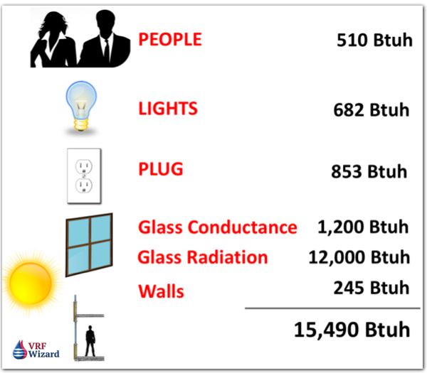
People

2 People x 255 Btu/Hour = 510 Btu/hour

Lights

2 Lights x 100 Watts/each = 200 Watts x 3.41 Btu/Watt = 682 Btu/Hour

Plug Load

2 Plugs x 125 Watts/each = 250 Watts x 3.41 Btu/Watt = 853 Btu/Hour

Solar – Conductance thru Glass

Assumes 200 Ft2 wall with 30% glass.

Q = 0.80 (U-Factor) x 60 Ft2 (30% of 200 Ft2) x 25 (Temp Diff Outside – Inside) = 1,200 Btu/Hour

Solar – Radiation

Q = 60 Ft2 x 0.8 (SC) x 250 (SCL) = 12,000 Btu/Hour

Solar – Conductance thru Wall

Q = U x A x CLTD

Q = 0.07 (U-Factor) x 140 Ft2 x 25 TD = 245 Btu/Hour

Total Sensible Cooling Load

calculating cooling load
Total Sensible Cooling Load

How to Determine Room CFM

The following calculation can be done after you have done your cooling load calculation to determine your total sensible load.

CFM = Q / 1.08 x (EAT – LAT)

CFM = Cubic Feet per Minute

Q = Btuh (Solved above = 15,490 Btuh)

EAT = Entering Air Temperature (Room Temperature 75 F Degrees)

LAT = Leaving Air Temperature (Supply Air Temperature 55 F degrees)

CFM = 15,490 Btuh  / 1.08 x (75 F – 55 F)

CFM = 15,490 / 1.08 x (20)

CFM = 717


Items not Considered in the above Sensible Heat Calculation

Infiltration

This is the air that makes its way into the building unconditioned, under exterior doors, through window frames or building cracks.

Ventilation (Outside Air)

This is air brought into the building for health reason. Ventilation codes require so much outside air for every person based on occupancy type or by building use. This ventilation air adds additional loads to the air conditioning system, including the addition of latent load (moisture) that must be removed at the cooling coil. Using VRF in some jurisdictions allow for reduced levels

You can also watch our YouTube video on this topic Cooling Loads

Subscribe to our mailing list

* indicates required


MEP Academy Online Courses
HVAC Sheet Metal Courses Online

ZoomLock Value Calculator Review

0
ZoomLock Value Calculator Review

ZoomLock Value Calculator Review

The ZoomLock Value Calculator provides a quick way to analyze the cost difference between doing a project with brazed joints versus the ZoomLock press-fit connection method. In this article we will do a ZoomLock Value Calculator Review based on their online downloadable 2017 version of the calculator. If you want to follow along with this example, download the ZoomLock Value Calculator from the below link;

http://sporlanonline.com/zoomlock/value-calculator/ (2017 version)

ZoomLock Input Sheet

The following ZoomLock Value Calculator Review is based on the default values that come from the 2017 ZoomLock Calculator when you download it. We compare the default values against our values for the possible scenarios you may encounter in real life. We haven’t changed any of the default values in the screen shots of the ZoomLock calculator unless indicated otherwise.

ZoomLock Value Calculator Review
ZoomLock Value Calculator

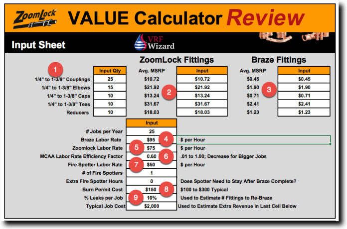
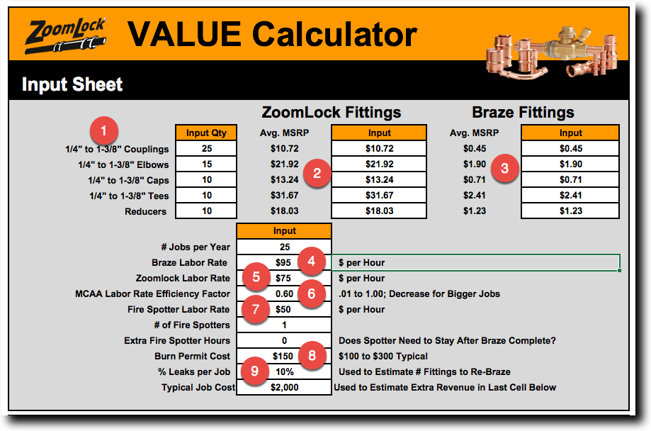
As you can see from the screenshot above the ZoomLock Calculator groups all of the different sizes for a single fitting type together (Item #1). Such as, 1/4” to 1-3/8” Couplings have one unit price value. The material multiples shown in the ZoomLock Calculator based on one of each type fitting are as follows;

  • Couplings 24x (This means that a ZoomLock fitting cost 24 times that of a brazed fitting)
  • Elbows 12x
  • Caps 19x
  • Tees 13x
  • Reducers 15x

The average cost for one of each ZoomLock fitting type was 14x times that of a brazed fitting. Based on the quantities used in the above example the cost multiple is closer to 15x. The average cost multiple will depend on the various quantities of the different sizes and types of fittings needed for your project. (See our article on ZoomLock Cost Analysis)

My experience reflects a greater multiple for the couplings material cost impact. I show a multiple of 30x on average for the couplings through all size ranges on my most recent project, but maybe you will get a better price from your supplier. Its basic math, so check your material cost multiples.
What the ZoomLock calculator shows is that couplings are the most expensive fitting followed by Caps, Reducers and Tee’s with Elbows being the least expensive. Based on this, the more couplings you have the higher your material cost difference will be.

ZoomLock Calculator Input Values

Labor Rates

The ZoomLock calculator shows the default labor rates as $95/Hour (Item #4) for brazing and a $75/hour (Item #5) rate for a ZoomLock fitting. For our cost analysis we used the same labor rate for both. You can change these values to reflect your crew rate. We also used the fire spotter at $50/hour (Item #7) or less when the field rate was lower than this in our evaluation.

Typical Job Cost

Remove this value ($2,000) as it doesn’t affect our analysis.

MCAA Labor Rate Efficiency Factor

MCAA (Mechanical Contractors Association of America) is a trade organization that makes available labor unit values for thousands of pipe, valve and fittings based on contractor surveys. An MCA labor factor of 1.0, means that the unit of labor is straight out of the book without any adjustments. The factor takes into consideration basic assumptions about job conditions, which are too many to list here. Contractors adjust up or down this factor based on the differences in the project they are bidding versus the MCA labor factor from the database. If the current project seems much easier than the factor is discounted, or if the project conditions are more difficult the factor is increased.

The ZoomLock calculator comes preset with a discounted MCA factor of 0.60 (Item #6), which amounts to a value 60% of what is considered the standard at 1.0. If you know how you perform against the MCA benchmark factor of 1.0 than this is an easy adjustment for you. If you’re unfamiliar with the MCA labor factor rates, than this could be a little challenging to understand.

Fire Spotter Time Overstated

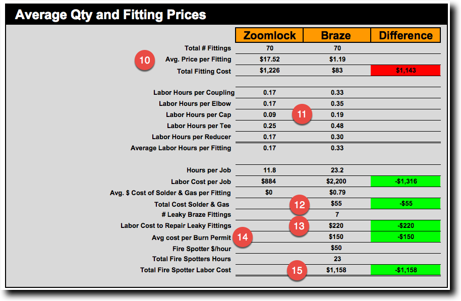
The ZoomLock calculator is made so that if you enter values for a Fire Spotter (Item #7 & 15) and Burn Permit (Item #8 & 14) their fitting will always appear to be more financially feasible. This is because every hour you have of brazing they include a matching hour of fire spotter time (Item #15). So if you have 100 hours of brazing the ZoomLock calculator default setting figures an additional 100 hours of Fire Spotter Time (Item #15), which equals 200 hours compared to only 100 hours for ZoomLock.

They have put a lot of weight on the fact of using a fire watch and burn permit. They use a 1:1 ratio, meaning one fire spotter for every hour of labor for installation. On larger projects this ratio will obviously be less when working in the same area optimizing the fire watch.
The reason using a 1:1 ratio is excessive and overstated is because the MCA labor units include much more than just brazing. It includes labor task that have nothing to do with brazing and for which a fire watch or burn permit isn’t required such as;
MCA Labor Units for a Brazed System includes;

  • Receiving
  • Unloading
  • Stockpiling
  • Distribution
  • Handling and erection
  • Fitting & Joining. (Fire Spotter Required)
  • Pressure Testing

So adding an hour of fire spotting time for every hour of installation is unwarranted and confuses the cost analysis. We will use 25% of the installation time for the fire spotter and recalculate everything with and without certain percentages of brazed fitting leakage.

Burn permits are required on projects that use an open flame such as brazing or welding, often requiring the Fire Spotter to remain 30 minutes after the last braze.

Assuming that you don’t pay the person doing the fire watch any more than the installer, we can than find a breakeven labor rate using the same labor rate for everyone including the fire watch, unless we exceed the $50/Hr default setting, at which point we will hold at the $50/hr rate for the fire spotter. There are a lot of people who would stand around looking for a fire hazard for $50/Hr or less.

We will also use 25% of our total hours as the time required for the actual brazing that requires a fire watch. The rest of the time is comprised of the other task related to the installation as outline above.

Breakeven Labor Rate

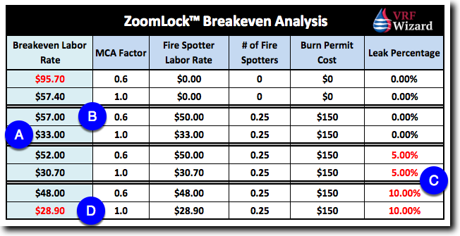
This is the minimum hourly rate that you must pay your crew in order to make the cost premium for ZoomLock™ fittings to pay for themselves through labor savings based on the different scenarios as shown in the table. This is the point at which material and labor when added together is the same for either a ZoomLock or Brazed fitting.

ZoomLock Calculator Review

At an MCA factor of 1.0 this makes the breakeven labor rate at approximately $33/Hr, (Item “A”) assuming no leaks. So if you pay your workers $33/Hr or more, than using ZoomLock under these conditions makes financial sense. Let’s look at an MCA labor factor of 0.6 (Item “B”) the default setting.

With the same parameters as the above, except with a 0.6 MCA factor, we get $57/Hr as the labor rate breakeven point. So, if you pay your workers $57/Hr or more under the above conditions using an MCA factor of 0.6, than once again ZoomLock™ makes financial sense, anything less than brazing would be least expensive.

For a Union company these labor rates make a lot of sense, making ZoomLock™ a great solution, but for the non-union companies, your labor rates are going to be the major deciding factor. And if the breakeven point is close and leaning towards brazing, it may still make sense to go with ZoomLock™ for several other reasons, such as shifting the risk of labor cost and avoiding the ramifications from using an open flame as previously discussed in other articles.

Basically, the higher your labor rates the more financially feasible ZoomLock™ becomes. The higher labor rates offset the higher material cost, as it takes more labor for brazing while costing more for ZoomLock™ materials.

Brazed Fitting Leakage Percentage

The ZoomLock™ calculator comes with a default setting of a 10% leakage rate (Item #9) for brazed fittings. This adds another 10% (Item#13) of the brazed labor cost to the cost analysis. We rerun the calculations with a 5% and 10% leakage rate (Item “C”). If your leakage rate is any higher than that, you probably need to practice more, or just give up and go with flared fittings or a press-fit joint.

Brazing requires practice and understanding the proper preparation techniques to ensure a leak free fitting. The same is required for the ZoomLock™ fitting but to a much lesser degree. Each connection type requires that you follow proper protocol as dictated by the manufacture for a leak free joint.

As can be seen in the example, adding a 5% leakage rate to the two different MCA Labor factors will drive up the cost of brazing and lower the breakeven labor rate at which ZoomLock™ becomes feasible. And by increasing the leakage rate to 10%, the breakeven labor rate is reduced more, so that under the most extreme conditions of this analysis, a rate of $28.90 (Item “D”) can get you either method at the same cost. Anything above $28.90 leans towards the ZoomLock™ fitting at this last condition.

ZoomLock Average Fitting Cost

Summary

Determining if ZoomLock™ is feasible for your project will be based highly on your field labor rates, the requirement for a fire spotter, your MCA labor productivity factor and your leakage rate. All of these play into your analysis. We suggest you play with the ZoomLock calculator using different values that you believe represent your company’s profile. On a strictly financial basis labor rates will be the strongest influencer on feasibility.

Our ZoomLock Value Calculator Review has identified a Labor Rate range from a low of $28.90 to a high of $95.70 based on the MCA Labor Factor, Fire Spotter, Hot Permit Cost and the leakage rate from brazed joints.

Beyond the financial aspects of brazed versus ZoomLock™, there are many benefits to a non-flame approach that we have discussed elsewhere. We believe ZoomLock™ has a place in this industry and will only gather more market share as companies become aware of the benefits and the price difference decreases overtime.

Schedule a demo with your supplier and see for yourself how quickly and easily a joint is made, and you may never turn back. This doesn’t mean you have to throw away your beloved torches, as there will always be a need to burn something.

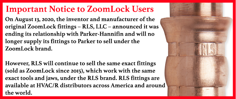
Important Notice for ZoomLock Users

Also checkout ASHRAE’s Study on Mechanical Piping Joints

Checkout our other ZoomLock Articles;

ZoomLock Kluake 19 kn Tool Review

ZoomLock Cost Analysis

ZoomLock vs Brazed Fittings

Also check out our article on the Lokring fitting which is another pressfit fitting, and the Reftekk Piping Solution which claims to reduce brazed connections by 75%, and the SmartLock fitting which claims to reduce labor by 90% over brazed.

ZoomLock™ is a trademark of the Parker Hannifin Corporation.

ZoomLock™ Value Calculator Version 2017 downloaded 11-7-17

Subscribe to our mailing list

* indicates required


Refrigerant Leak Detector

0
Bacharach - Refrigerant Leak Detector

Refrigerant Leak Detector

The Bacharach MVR-300 Refrigerant Leak Detector is described below. Also available in the link below is the specification sheet for the newest VRF Refrigerant Leak Detector to the market, the SensAC.

Alarms

You can have the alarm shut down the fan coil and condenser, have it close solenoid valves and alert management through the BMS.

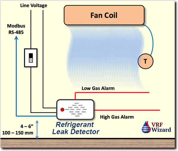
There are 2-Stages of Alarm as shown by the red line in the drawing which provides a low and high alarm. Default Alarm Ranges 0 to 10,000 ppm.

You can enable or disable the audible alarm by moving a dip switch.

Dip Switches to set: Alarm delay, Relay 1 (low gas alarm) , Relay 2, Alarm latching (Manual or Auto Resetting of alarm), Disable buzzer.

Detectable gases: R22, R32, R404A, R407C, R410A

Gas alarms and status messages are indicated visually by a 3-colored LED and audibly by a buzzer. In case of an alarm and/or fault, relay switch (for example, shut-off valves or alarm devices).

Refrigerant Leak Detector Approved Locations - Bacharach
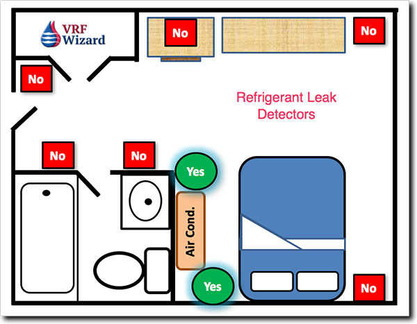
Refrigerant Leak Detector Approved Locations in a Hotel Room / Bedroom – Bacharach

Safe Mounting

Mount in-room sensors at less than the normal heights of occupants. E.g., in a hotel room this is less than bed height (between 100 and 150 mm (4 and 6 inches) off the floor). Avoid drafts and heat sources (like radiators), and avoid sources of steam.

This leak detector must be connected by a marked, suitably located and easily reached switch or circuit-breaker as means of disconnection.

Electrical Power and Control Wiring

  • 100 to 240 VAC Power is required. Maximum of 4 W operating power
  • Can be installed in a standard electrical box
  • Control Wiring – Relay 3-core, 18 to 20 awg, Modbus Network 2-core twisted pair shielded cable 18 to 24 awg

Physical Properties

Size 6” x 4.1” x 1.75” (150 x 105 x 45 mm)
Weight 8 oz (230 grams)

Maintenance & Life Cycle

  • Sensor Life: 5 to 8 years
  • Recommended to test and recalibrate every 6 months.
  • The detector can be calibrated and maintained non-intrusively using a magnetic wand.
  • Based on the Bacharach MVR-300 Refrigerant leak detector

Connecting to a VRF / VRV System

Connect directly to the T1 & T2 terminals on a Daikin VRV fan coil to shut down outdoor and indoor units. You can use the output signals from the Refrigerant leak detector to close solenoid valves to isolate the rest of the system from dumping the total refrigerant charge into the space. Check other VRF manufactures for the proper locations for connecting alarm inputs for shut down and alarming.

If you just shut down the indoor and outdoor units, the remaining refrigerant in the system is still at a higher pressure than that of the space, so it will seek to equalize the pressure, basically dumping the remaining refrigerant into the space.

The leak detector alarm relays can be used exclusively to inform the occupants and the building manager of the refrigerant leak with a visual and audible alarm.

You could have the Bacharach refrigerant leak detector shut down the indoor and outdoor unit and use a solenoid valve to isolate the refrigerant piping. Just be careful to check with the design engineer anytime you put an inline device, like a solenoid valve in the refrigerant piping as this can affect the system performance.

See our other article on refrigerant leak detectors that explains the requirements of ASHRAE 15 and other information.

Startup and testing of the Refrigerant Leak Detector

You can go through the complete process of calibrating the sensor on the Bacharach Refrigerant Leak Detector, spending the time to hookup the gas and hose or you can pay a little extra and purchase a pre-calibrated sensor which retails for around $85. This will save you from 20 to 30 minutes on each refrigerant leak detector and make the startup process faster. The sensor module is replaceable.

VRF Refrigerant Leak Detectors

The Bacharach Refrigerant Leak Detector List Price is $299.00 (Check with your supplier for your discounted amount)

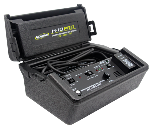
This is a Bacharach 3015-8004 H-10 Pro Refrigerant Leak DetectorBacharach Leak Detector H-10 PRO

The SensAC VRF Refrigerant Leak Detector is available from Unlimited Controls.

SensAC VRF-Refrigerant Leak Detector

Subscribe to our mailing list

* indicates required


ZoomLock Cost Analysis

0
ZoomLock Fitting Cost Analysis

ZoomLock Cost Analysis

Determining if there is value in using a press-fit joint such as ZoomLock™ requires that you look at several factors that impact cost and quality. We covered the technical aspects of ZoomLock™ in another article; see ZoomLock vs Brazed for additional information. In this article we are strictly looking at this from a financial perspective. We try to answer one question in this ZoomLock Cost Analysis, ‘Does ZoomLock make financial sense for your business?

(Click here to enlarge Infographic)

ZoomLock Fitting Cost Analysis Infographic

Share this Image On Your Site

ZoomLock Value Calculator

Be careful when using the online downloadable ZoomLock™ value calculator as it appears to us that they have over inflated the time it takes to make a brazed joint. They are showing that the ZoomLock joints take about 25% of the time as a brazed joint, or the equivalent of a 75% savings. This even contradicts their literature that claims a 60% savings.

There are also many versions of the ZoomLock Calculator available when doing a Google search. Here are two versions of them;

1) http://sporlanonline.com/zoomlock/value-calculator/ (2017 version)
2) ZoomLock Value Calculator 2016 (Direct download of an Excel file) Google for file.

The ZoomLock calculator also uses $95/Hr for brazing and $75/Hr for their fitting. This reflects the lower skill level required to make a ZoomLock joint compared to that for a brazed joint.

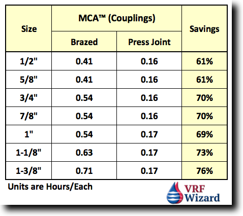
When I look at the MCA database and do the calculations I find a different value, ranging from 61% to a 73% savings based on size. This is strictly based on the labor unit values in the MCA database for “OD Size Wrot/Cast Copper Fittings” and “Ridgid ProPress”. MCA doesn’t have ZoomLock values, so ProPress values are used which is basically the same setup and procedure for a press-fit joint. For our example I’ll use “Couplings” (Unit values are in hours/each fitting)

ZoomLock Labor Units - MCA
ZoomLock vs Brazed MCA Labor Units

One of ZoomLock’s online video’s shows that they can do 8 joints to a single brazed joint, which implies an 87% savings. There appears to be some inconsistency in ZoomLocks marketing on their websites, downloadable calculator and various publications of just how much labor you can save using their fittings, but there is no denying the fact that you will save time with their system.

It’s important to establish the basis’s of comparison and the unit values that are used in any analysis. We’ll use a 60% savings in our cost analysis as this matches the MCA database and ZoomLock’s published data. It’s also important to note that your values will differ based on the skill level of your installation personnel. The unit values above have assumptions based on standard working conditions, and the unit values include receiving, unloading, stockpiling, distribution, handling and erection, fitting and joining and pressure testing.

MCA – Mechanical Contractors Association

For those of you who are unfamiliar with MCA (Mechanical Contractors Association), they are an industry organization who as part of their service provides publications, training and a database of labor units garnered through contractor surveys. If you own a commercial HVAC company and use estimating software for piping takeoff’s, then its most likely that you have the option of using MCA as a choice for your labor unit values.

ZoomLock™ Fitting & Labor Cost

In our ZoomLock Cost Analysis we look at the two main costs that impact the financial decision on whether to use ZoomLock™ fittings, one is labor and the other is the cost of the fittings and tools. The cost of the fittings differs from the cost of the tools in that the fittings are a direct cost charged to a certain project, while the tools are a capital asset that can be used on multiple projects and will be depreciated over time.

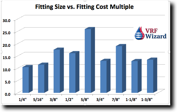
ZoomLocks Value Calculator (2017 Version) shows that their fittings cost anywhere from 11 to 24 times that of an OD wrot copper fitting, your cost could be different based on your companies buying power and the discount your supplier provides you. Their average cost is 15x times that of a brazed fitting. We’ll use an average of 14 times for this example.

ZoomLock Fitting Price Analysis

ZoomLock™ Installed Cost

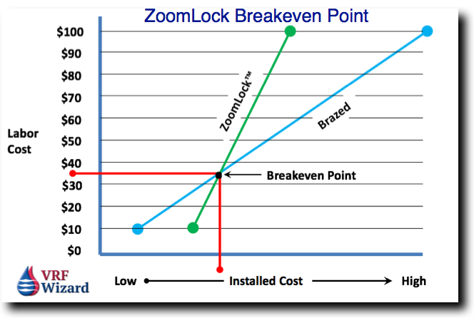
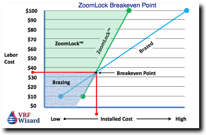
Comparing ZoomLock™ to Brazing reveals that at some point there will be an intersection or breakeven point between the two systems. In the situation where labor rates are low, the extra cost of the ZoomLock™ material will dictate that brazing is more cost effective. Likewise, as the labor rate increases, the cost of labor becomes the overriding factor, making ZoomLock™ the more cost effective solution due to its labor saving features.

ZoomLock™ Breakeven Point

The breakeven point is determined by three factors; material cost, labor rate and labor productivity. The breakeven point will differ from one company to another based on these factors. The two main variables are your company’s purchasing power with your vendor and the labor rates for field installation personnel. Your labor productivity should be close to the industry norms. The example in the chart shows a $35/hour breakeven point, which means anything above that crew rate for your installers would make ZoomLock™ financially viable. This is just an example and your breakeven rate will differ. Just realize that the breakeven point is going to be much higher than $35/hour for most companies. This example is strictly based on a financial analysis, exclusive of all the other benefits of using a non-flame fitting as discussed in a previous article. The breakeven point changes when you change the variables in the ZoomLock Value Calculator.

ZoomLock Cost Analysis
ZoomLock Fittings Breakeven Analysis

Fitting Cost Variance

Based on which size fittings are part of your project, the cost various. The most common and highly manufactured OD Wrot Copper brazed fittings drop in price based on size, so a larger fitting size could actually be less costly than a smaller fitting. In these cases the cost difference between ZoomLock™ and brazed fittings increases, causing the chart below to look more like a stock on Wall Street than a straight line. This is shown by looking at the 5/8” fitting size to notice that the difference between ZoomLock™ and brazed is at its greatest. ZoomLock™ fittings increase in cost sequentially with the fitting size.

ZoomLock Fitting Sizes vs Cost Multiplier

Other Considerations

Since this report is based solely on a financial decision we won’t go in depth on the other considerations when making a decision to use ZoomLock™. Putting cost aside there are many benefits to the use of ZoomLock™ or press-fit fittings when installing refrigerant piping. Labor is the obvious advantage, but others such as we covered in our previous article entitled “ZoomLock vs. Brazed”. These advantages include no need for a hot working permit, reduced risk of fires from a brazing torch, no smell from a torch or the accidental setting off of smoke detectors, or the use of a nitrogen purge.

Summary

Our ZoomLock Cost analysis believes that ZoomLock is a financially viable alternative when labor rates and labor productivity are high enough to offset the additional cost of the special fittings. The breakeven point is determined by the cost of material, labor rates and labor productively. The analysis doesn’t take into consideration varying jobsite conditions that could make either of the options undesirable for many reasons, such as space restrictions, building construction material types, occupancy type and facility protocols when using an open flame tool.

ZoomLock Fittings vs Brazed

Based on our ZoomLock Cost Analysis we definitely recommend that you call your local ZoomLock™ distributor and get a free demo, it just may be the next generation of joints with the greatest growth potential, and if your customer has seen an advertisement about it and is more aware then you are, that’s embarrassing. Also, see the SmartLock Fitting for additional labor savings according to its manufacture.

Important Notice for ZoomLock Users

Checkout ASHRAE’s study on Mechanical Piping Joints.

For additional information see our article ZoomLock vs Brazed Fittings or our review of the ZoomLock Value Calculator and our ZoomLock Klauke 19 kn Tool Review

Also check out our article on the Lokring Pressfit Fitting , SmartLock Fitting and Reftekk Bendable Piping.

HVAC Estimating spreadsheet

Subscribe to our mailing list

* indicates required