


Manufactures VRF Piping Layout Drawings
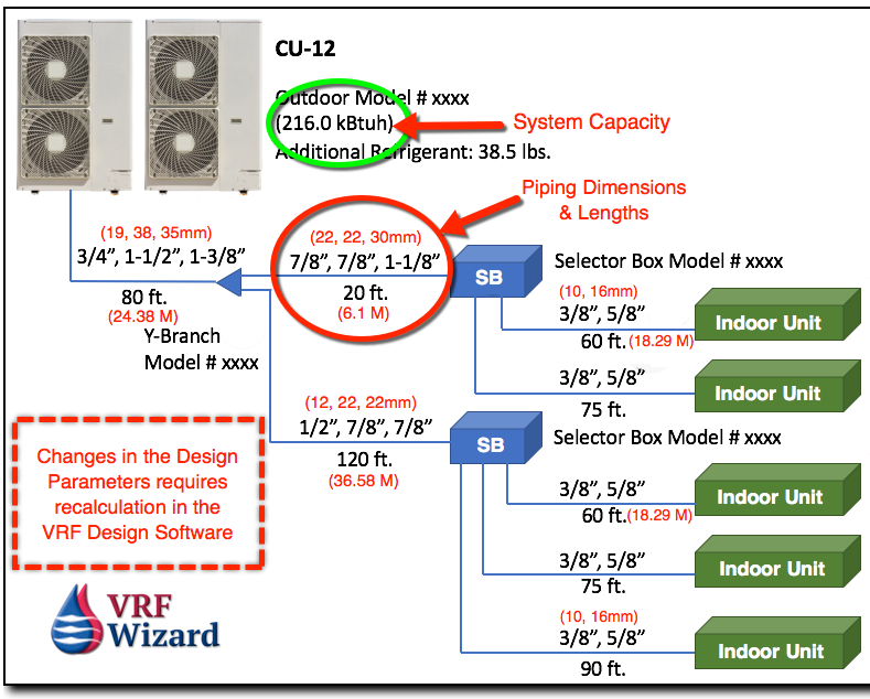
The VRF Piping Layout is highly engineered by the VRF manufactures software to design the pipe sizes to meet the capacities and conditions required, including ASHRAE 15. The pipe sizes are affected by capacity, pipe lengths and the quantity of fittings. When any of those factors change than the design engineer needs to enter the new parameters into the piping design software to recalculate the new requirements. The changes could affect the sizes of the pipes required and the refrigerant charge.
When Should You Recalculate
When doing a VRF project the installing contractor is most likely working off of either a designed floor plan without sizes shown, in which case the piping schematics provided by the VRF manufactures software program are used for the correct pipe size. The VRF manufactures piping schematic is based on the capacity, design piping lengths and quantity of fittings. If any of these factors change then the calculation for pipe size must be recalculated using the VRF Manufactures software program.
If you have a VRF piping layout (schematic) showing that you have a 1-ton indoor unit that requires a 1/4” (6.35mm) liquid line and a 1/2” (12.7mm) gas line based on the pipe length being 20 feet (6 meters) from the branch selector box with 2 elbows, but due to field conditions you actually have 40 feet (12.19 m) of pipe and 6 elbows, then you will need to give this information to the design engineer to put into the VRF manufactures software to recalculate the required pipe size. It’s possible that no increase in size will be required, but if it is required, and you don’t make the change, you will reduce the capacity of the indoor unit.
The installing piping crew must follow the VRF manufactures piping schematic and provide any changes to the design engineer before installation begins. Not only do additional lengths of pipe impact the pipe size, but the total refrigerant charge required. The amount of refrigerant in a VRF system is critical to a successful system, so any changes to lengths is very important. The actual length to be installed is the only accurate method of getting the proper refrigerant charging amount.
Of course, you need to make these changes before installing any of the piping in case changes are warranted.
You might have noticed that we have mention multiple times the need to recalculate if there are any changes, that’s due to the importance of this in VRF System Design and installation.
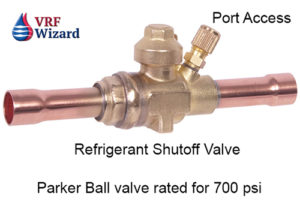
Full Port Refrigerant Ball Valves
Using full port refrigerant ball valves with Schrader ports allows for isolation of any indoor unit without having to shut down and drain the complete refrigerant from the system. Make sure to check with the design engineer for the approved location of the ball valves in accordance with the VRF manufactures design guidelines.
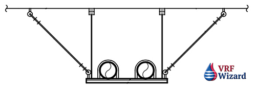
Refrigerant Piping Supports & Seismic
Consideration must be made for how you will support long runs of piping inside the building or outside on the roof or up a shaft, etc. Will you use a B-Line Dura-Blok for piping supported on the roof as shown below? Will you use single point hangers or a trapeze?

Do you live in an area known for earthquakes? Do you need to comply with seismic restraint requirements? If so, you might need something similar to this detail. SMACNA provides guidelines on the installation of seismic restraints. The piping below is shown supported on unistrut rack, with vibration isolation springs and seismic cables.
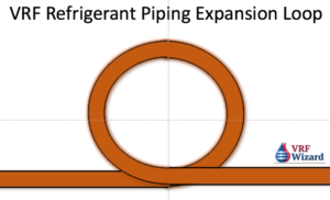
Expansion Loops
Review our article on the use of expansion loops for long piping runs to avoid pipe ruptures due to expansion. Check with the design engineer for this requirement on your project.
VRF Startup & Commissioning
The VRF system price often includes a Factory representative to assist with the startup and commissioning of the system. This individual will want to ensure that the system has the appropriate refrigerant charge.
It’s important not to energize the power to any of the equipment before the piping is installed if you are using a nitrogen purge with brazing. Energizing the equipment could cause the EEV’s to close, preventing the nitrogen purge from doing its job.
VRF Piping Fitting Types
There are many ways to make a piping connection, including Brazing, flaring and pressfit. Checkout our article on the ZoomLock fitting versus Brazing and our ZoomLock Cost Analyses,, Reftekk Piping Solution, and LokRing Fittings
Special VRF Piping Requirements
- Use dedicated R410A refrigerant hoses
- Dedicated R410A flaring tool. Flares are deeper due to increased operating pressure.
- All pipes get insulated.
- Y-Branch when installed horizontally. LG allows a +/- 10 degree rotation from the horizontal plane, Daikin allows up to +/- 30 degrees.
- Confirm minimum distances between fittings. LG is 20” (508mm)
- Avoid creating oil traps. If required use inverted trap within VRF manufactures guidelines.
- Headers have to have homeruns to Indoor Units, without other Y-Branches or Headers in-between.
- Use a torque wrench for proper tightening of flared fittings to prevent leaks.
- Use dry nitrogen purge when brazing.
- Use expansion loops for long runs of piping.
- Minimize piping lengths and fittings.
- Report back to the Design Engineer any changes in the system installation.
Checkout Job Walk Basics 101 – What you need to know when attending a job walk on a retrofit project.


