Home Blog Page 6

DOAS Energy Recovery

0
doas energy recovery

DOAS – Energy Recovery

When is an Energy Recovery system required according to ASHRAE 90.1 (2013)?

ASHRAE 90.1 2013

(Energy Standards for Buildings, Except Low Rise Residential Buildings)

When using a VRF Dedicated Outside Air System (DOAS) to bring in ventilation air to satisfy ASHRAE 62.1, you need to consider Energy Recovery. ASHRAE 90.1 defines the requirement to install an energy recovery system based on climate zones and the total percentage of outside air in relationship to the total Supply CFM.

The higher is the percentage of outside air to supply air, the greater the requirement for energy recovery.

According to ASHRAE 90.1 “Each fan system shall have an energy recovery system when the system’s supply airflow rate exceeds the value listed in Tables 6.5.6.1, based on the climate zone and percentage of outdoor airflow rate at design conditions.”

There are ten (10) exceptions to this standard so be sure to look them over if implementing this strategy would be difficult for your project.

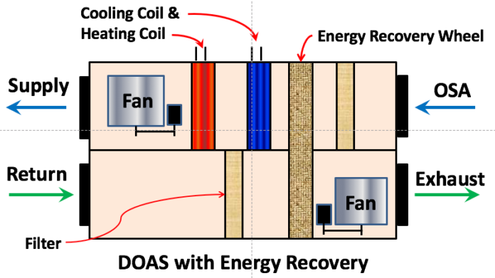
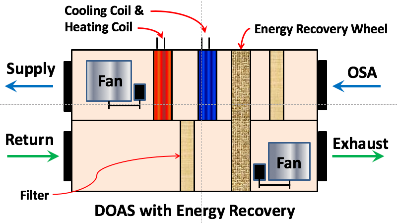
DOAS Energy Recovery Wheel

The energy recovery wheel transfers energy from the air stream leaving the building to the air stream entering the building in heating season. As the return air enters the energy recovery wheel it comes in contact with the surface area of the moving wheel.

This portion of the wheel absorbs the higher energy and then releases it on the other side to the lower energy outside air entering the building for ventilation.

The energy transfer is the opposite for the cooling season, where the heat entering the building for ventilation gives up its higher energy to the cooler, lower energy return air being exhausted, thus cooling the outside air.

doas energy recovery

Sensible vs Latent Heat Transfer

One aspect of the heat transfer will affect the temperature of the air entering or leaving the building. This involves the sensible heat, which is measured by the dry bulb temperature in Fahrenheit or Celsius.

The standard wheel accomplishes the sensible heat transfer, but for latent heat transfer you need a desiccant wheel. The desiccant will absorb the moisture from one air stream, the higher vapor pressure air stream and release it to the lower vapor pressure air stream.

Its basic physics which we don’t have to fully understand to appreciate the beauty of, or how it can save energy and money for your customer.

Energy Recovery System Effectiveness

Per ASHRAE 90.1 “Energy recovery systems required by this section shall have at least 50% energy recovery effectiveness. Fifty percent energy recovery effectiveness shall mean a change in the enthalpy of the outdoor air supply equal to 50% of the difference between the outdoor air and the return air enthalpies at design conditions.”

On your next VRF project where you are contemplating using a Dedicated Outside Air System (DOAS), checkout energy recovery as an option.

Please leave us a comment on projects or your thoughts on the use of energy recovery in VRF projects.

Be sure to checkout our time and money saving spreadsheets;

  1. VRF System Installation Cost Estimating Spreadsheet
  2. VRF System Installation Budgeting and Historical Cost Database Spreadsheet

HVAC Estimating spreadsheet

Subscribe to our mailing list

* indicates required


VRF Ventilation

0
VRF Ventilation

VRF Ventilation

The building requirement for ventilation air and the methods of delivering this air vary by geographic location. We’ll discuss several methods commonly found in various region of the United States. Indoor air quality (IAQ) is important for occupant health and productivity, in addition to be mandated by most codes, unless your outside air can be proven to be too polluted in which case you can possibly get a variance.

ASHRAE 62.1 Ventilation for Acceptable Indoor Air Quality

The purpose of the standard according to ASHRAE is to “specify minimum ventilation rates and other measures intended to provide indoor air quality that is acceptable to human occupants and that minimizes adverse health effects.”

Minimum Ventilation Rates

Most states have minimum ventilation rates that apply to various types of buildings and spaces within those buildings. Common sense tells you that a hair salon would have a higher ventilation rate then an office space. A beauty and Nail salon could require 25 CFM/person compared to the common area in a shopping mall which may only require 9 CFM/person. The CFM/person factors take into account the density of people for the type of space and for the off gassing of furniture and construction materials.

Maintaining a minimum ventilation rate helps ensure a minimum level of fresh outside air is delivered to the space. The more outside air brought into the space the larger the air conditioner required to handle the additional load.

VRF Ventilation Methods

There are five basic methods of bringing in VRF ventilation air to a VRF system as follows.

DOAS – Dedicated Outside Air System

The DOAS unit filters and pre-conditions the VRF ventilation air. One of the benefits of using a dedicated Outside Air System that has pre-conditioning included is that it takes the ventilation load off of the indoor fan coil unit. The DOAS is sized just to handle the VRF ventilation load and not the full cooling or heating load of each space, this helps reduce the size of the unit. There are two commons methods of DOAS, as follows;

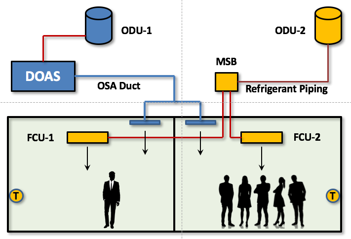
VRF DOAS De-Coupled System

Decoupled Dedicated Outside Air System. This system provides VRF ventilation air directly to the space and not directly to the Indoor Fan Coil Unit. The VRF ventilation air doesn’t directly Passover the Indoor Unit coil but instead is delivered through a grille or diffuser, or dumped into the return air attic for that fan coil.

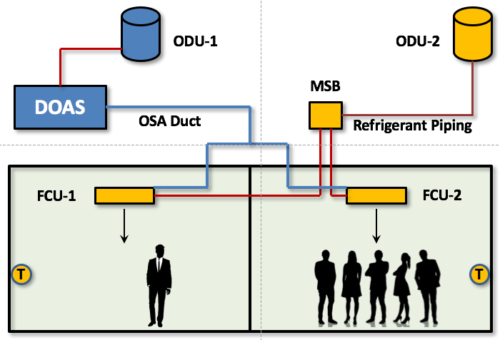
VRF DOAS Coupled System

Coupled Dedicated Outside Air System. This system provides VRF ventilation air directly to Indoor Fan Coil Unit or the return air duct; hence it’s coupled with the unit. This provides a direct path to the unit. Unfortunately not all indoor fan coil units are made to accept a direct outside air connection.

The decoupled method avoids return air filter blow back caused when the fan coil unit is off and the DOAS is running when using the coupled method. Either way, consideration must be made for controlling the DOAS when the indoor fan coils are in off mode. Otherwise you run the risk of blowing the OSA through a system that is in the off mode. This can be accomplished with motorized dampers on each branch duct feeding a fan coil or space.

VRF Ventilation Air Ducted Directly to Indoor VRF Unit

With this method you duct straight to the indoor unit or return air duct without the benefits of a VRF DOAS unit. There is no pre-conditioning of the VRF ventilation air, so the indoor unit will need to handle the load created from this unconditioned air.

Natural Ventilation

The use of operable windows might be acceptable for your exterior zones. Check with your local governing authority. There are some challenges if the outdoor air has high moisture content. The indoor unit will need to be up sized to handle the additional load caused by the unconditioned outside air.

Also, depending on your energy code, you could be required to provide a window switch that shuts off the Air Conditioner when the window is opened.

VRF Ventilation with Fan Assisted Outside Air

Another method would be to draw VRF ventilation air into the room through a louvered opening with a fan. The fan can exhaust air from the space by pulling outside air through a filtered louvered opening. It’s important to use filtration to avoid bringing pollutants into the space.

ERV – Energy Recovery Ventilator

Similar to the method above, except that you could use an Energy Recovery Ventilator (ERV) to pull in outside air while exhausting conditioned air through the same device. The ERV will recover some of the heat that otherwise would have been lost by the exhaust fan.

Economizers

In states like California you can get away from the Title-24 requirement of an economizer by using one of the allowable exceptions. One of those exceptions is to increase the efficiency of the air conditioner over the benchmark standard. In some regions this equates to a 30% increase in efficiency over the benchmark required to avoid complying with the code mandated economizer. Using a VRF system is one of the way’s to bypass the requirement for an economizer.

See how ventilation, People, Equipment and Infiltration affect VRF Ventilation and Sensible Heat Ratio.

Check out How to Calculate Cooling Loads. or VRF Ventilation and Sensible Heat Ratio

HVAC Estimating spreadsheet

Please leave a comment about your experience with VRF Ventilation. Were always happy to hear about your experience and share it with others.

Subscribe to our mailing list

* indicates required


What is VRF

0
What is VRF Air Conditioning

What is VRF

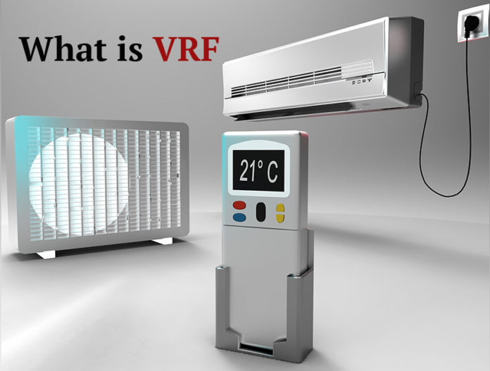
VRV Variable Refrigerant Volume systems were invented in Japan in 1982 by Daikin and brought to the United States in 2004. These systems are used worldwide. Daikin VRV (Variable Refrigerant Volume) is their trademarked name, that’s why all other manufactures use the acronym VRF.

Major Components of a VRF System

VRF systems include two major components, a compressor with outdoor coil and multiple indoor fan coil units. The outdoor unit houses the compressor which acts as a pump pushing refrigerant through piping to the indoor coils and back.

A third component is the VRF Branch Selector Box which is the traffic cop of the refrigerant, based on the demand of the system. See our article on VRF Single Port versus Multiport Branch Selector Boxes.

The outdoor coil is most often air cooled, or in some cases water-cooled with a connected cooling tower and boiler to maintain a minimum range of temperature. The compressor provides a variable flow of refrigerant by using an inverter rated motor that varies the speed of the compressor, allowing for reduced energy consumption and varying loads within the building.

Types of VRF Systems

VRF comes in three common system types, cooling only, VRF heat pump and VRF heat recovery. Cooling only is just as the name implies with no way of providing heat.

The heat pump system can provide cooling and heating, but only one method at a time, meaning all zones need to be either cooling or heating, not simultaneously.

The third type is the heat recovery system which allows for simultaneous cooling and heating, and provides for some great energy savings the more balanced the cooling and heating loads are. VRF Heat recovery units basically take heat from one space that wants to be cooled and gives it to another space that wants heating.

Also, within these VRF system types there are air-cooled and water-cooled outdoor units.

Types of VRF Fan Coils

The indoor units are called fan coils because they contain a fan and a coil. The coil can be used for cooling or heating depending on the type of system installed as indicated above. The indoor fan coils come in a variety of configurations and are either visible or hidden behind the construction.

The air can be ducted or un-ducted, meaning the air travels through a piece of sheet metal before reaching the conditioned space or the fan coil is exposed within the room and requires no ductwork.

The fan coils can be recessed mounted on the ceiling or they can protrude down from the ceiling, they can be floor mounted in the space with a manufactured cover or floor mounted and hidden behind construction materials, or hung exposed on the wall.

VRF Ventilation Requirements

Since these VRF fan coils are split from their outdoor units they need a source of fresh air which is important for air quality, unless you live in a heavily polluted city. ASHRAE and most codes require some form of outside air for ventilation, whether by natural means, such as operable windows or more commonly by a dedicated outside air system (DOAS).

This HVAC (Heating, Ventilating and Air Conditioning) unit can be fitted with a cooling or heating coil depending on the geographic climate conditions. The DOAS unit is not intended to cool or heat the space, but to provide fresh outside air that is tempered close to room conditions so that the outside air doesn’t add additional load to the indoor fan coils.

The load for this ventilation requirement should be handled by the DOAS. There are several methods or system configurations in the design of the DOAS that we’ll cover in another article.

VRF Energy Recovery

Working in conjunction with the DOAS unit can be some form of ERV (energy recovery ventilation) unit, that recovers heat from air being exhausted as in winter or from outside air when cooling.

In summer when the hot outside air that is required for ventilation is being brought into the building it can be run through the ERV energy recovery ventilation unit which has cooler indoor air being exhausted through it, effectively pre-cooling the hotter fresh air.

Conversely in winter when colder outside air is being brought in for fresh ventilation requirements, the warmer air being exhausted can be put through the ERV energy recovery ventilation unit to recover some of the heat energy to pre-heat the colder air.

The control of these systems range from a simple remote to complete integration into the buildings energy management system. The great thing about the VRF control system is that it doesn’t need any other automation systems, as it uses its own controllers and interface module with web access capabilities. See our comparison between VRF Manufactures.

How have you used ERV or DOAS in a VRF System, and did everything function smoothly?

Please leave us a comment below, and tell us about your experience with these systems.

Get this great book that goes in depth about VRF Systems.

Subscribe to our mailing list

* indicates required


MEP Academy Online Courses
HVAC Sheet Metal Courses Online

Panasonic Whisper Comfort ERV

0

Panasonic FV-04VE1 Whisper Comfort

Panasonic Energy Recovery Ventilator 100 ERV

0

Panasonic Energy Recovery Ventilator 100 ERV

Intelli-Balance(TM) 100 is well suited for single family homes and multi-family units. It is a customizable, powerful, high efficiency Energy Recovery Ventilator (ERV) that’s designed to help you meet ASHRAE 62. 2 ventilation requirements. This unique and cost effective Cold Climate ERV was manufactured for total versatility and installation flexibility, in a cold climate zone.

Energy is recovered from the exhaust air exiting the building, while the ventilation air absorbs this heat energy during the cold season.

For a larger commercial systems see the VRF DOAS Energy Recovery System. Read our article on VRF Ventilation for more information on how ventilation is handled on commercial projects.

VRF Project Video – Storage Facility

0

VRF Project Video – Senior Living Facility

0


Zoomlock or RLS versus Brazed Fittings and Joints

VRF Project Video – Shippensburg University

0

Installing VRF in a Senior Living Facility

0
Installing a VRF system in a Senior Facility

What are the difficulties of Installing a VRF system in a Senior Living Facility?

The difficulty with this VRF project is that the existing senior living facility is occupied. There are two buildings in this senior facility, one classified for independent residents, and the other for those needing assistance. Each building is three stories with long corridors. The existing system is comprised of window Air Conditioning units and hot water radiators. The corridors are currently unconditioned and are the subject of many resident complaints during the hot summer months.

VRF Engineering Challenges

VRF and ASHRAE 15

ASHRAE 15 limits the amount of refrigerant allowed in an occupied space, which will dictate the size of any one system. Since this isn’t classified as an institutional facility we can use the full amount allowed for R410A of 26 Lbs/ 1,000 Ft3 of space per ASHRAE 34. See article on VRF ASHRAE 15 for further explanation.

Project Construction Phases

The owner wants to do the project in two phases to match their financing and capital improvement budget. The first phase was to be the conditioning of the corridors where most of the complaints originated from, as the tenants already had window mounted air conditioners in their rooms.

The second phase would be the more difficult one of doing the dance around occupied senior tenant spaces to install the fan coils, condensate drain and controls. The project also included major renovations to the interior of the tenant spaces and the installation of a new fire sprinkler system. Total renovation budget is over $6,000,000, phased over several years.

Outdoor Unit Requires 50% Minimum Startup Load

Another important consideration when doing a phased project with a VRF system is that most require a minimum of a 50% load on the outdoor unit before you can start them up. Of course, after starting them up they can run at a much-reduced rate with the amazing energy saving aspect.

This provides a challenge for the phasing of the project and the relocation or disruption for the senior occupants as we would need at least half of the tenant spaces connected in order to start the system. This meant that we would need 50% of the tenant spaces connected in phase 1 or delay the startup of the outdoor unit until phase 2 of the project.

Single Port vs Multiport Branch Selector Boxes

Deciding on whether to use a VRF single port or multi-port branch selector box was made by the job conditions more so then any other aspect. The project conditions included, limited space above the corridor ceiling, in this case 6 inches because of the low floor to floor height and the need to share the space with lighting and the new fire sprinkler system.

The VRF multi-port branch selector box is much bigger than the single port box and would require furring down the ceiling; aesthetically unpleasing. The VRF multiport box would require multiple runs of refrigerant piping from the box to each tenant space, requiring much more attic space.

VRF Single Port Selector BoxThe decision was to use a VRF single port branch selector box after consulting with the client and the manufacture related to installing the piping without connecting the fan coils. The single port branch selector box saved the client some upfront cost until phase two of the project when they would be located within the tenant space, thus eliminating the space constraints of the corridor. This option only required us to run three main refrigerant pipes down the corridor with a Y-fitting at every location for a branch to the tenant space in phase two.

VRF System Oil Management

The manufactures concern was the management of the oil returning to the system, which requires avoiding any dead legs or capped piping branches which could potentially store oil in a pocket of the piping. The manufacture allowed the use of full-port Sporlan ball valves with taps at the Y-Branch fittings leading to the tenant spaces, with no piping extending off the mains. This would allow pressure testing, evacuating and charging the main pipes before installing any tenant fan coils, allowing the corridor renovation to be completed in phase one.

As part of phase one, we would install branch stubs into the tenant space for future connection. These stubs would not be charged, as they would be isolated from the main by the ball valves. Then during phase two, we would connect to these stubs and to the VRF single port branch selector box and tenant fan coil, pressure testing, evacuating and charging just the branch portion before opening the ball valve.

There is no way the tenants could stay in their rooms during construction unless they didn’t plan on coming out their rooms for the whole day, and the next two weeks that the corridor would be a mess of workers, ladders and tools.

Leading off with Asbestos Abatement

To make matters worse the corridor ceiling (Bottom of concrete slab above) was sprayed with asbestos in the old days, so this would need to be abated first. After the abatement, we would follow behind with our three main refrigerant pipes and Y-fittings.

The plan was to first do all the outdoor units including electrical, concrete pads and main refrigerant pipe up to where we penetrated the building before we started the tenant work. This would allow us to be ready as soon as we could get the mains run down the corridor and provide a 50% connected load.

Concerns of Management and Facility Staff

1. The management wanted to make the thermostats as simple as possible for the senior occupants to avoid unnecessary calls and complaints. This was easily accomplished by the options available for the face plate of the thermostat, which allowed for a version with as few buttons as possible, keeping it very simple.

2. They wanted to know how they would be notified if an error or VRF system alarm occurred. The main control panel has a feature that allows them to enter email addresses that will receive an automatic email alert on system alarm. The facility also wanted the Mechanical Company to receive the same notice and have a service vehicle in route as soon as the alarm message was received. This feature was also available within the control panel.

3. The senior facility was also concerned about the availability of trained service professional to respond quickly to any needed repairs or maintenance. This one will be based on your company’s service capabilities and their knowledge of VRF systems, for us this is not a problem as we have a large service fleet.

Summary of top 4 Challenges

1. ASHRAE 15
2. Requirement for 50% Load on Outdoor Unit
3. Occupied Senior Living Facility
4. Limited Attic Space above Corridor Ceiling.

Other Considerations

5. Simple thermostat for occupants
6. Fast response to system alarms.

The project description will be continued later in another project article.

Please leave a comment below and let us know some of the challenges of some of your VRF projects and how you overcame them. This will inform our readers of possible solutions to similar problems that they may be facing. As always, we appreciate your feedback and experience with VRF.

VRF HVAC Cost Budgeting Spreadsheet

Subscribe to our mailing list

* indicates required


VRF Single Port vs Multiport Branch Selector Box

0
VRF single port vs multiport branch selector boxes

When do you use a VRF Single Port vs Multiport Branch Selector Box?

What’s the difference between a VRF single port branch selector box and multiport box? What does the branch selector box do? Which one requires more piping?

The decision to use one or the other of these VRF branch selector box configurations is based on the site conditions and owner requirements. There are several factors to consider when laying out a VRF system and whether to use a multiport or single port branch selector box.

What’s Happening in the VRF Branch Selector Box

The VRF branch selector box is where the magic happens in the way of diverting the refrigerant based on the space requirements. The VRF branch selector box is the traffic cop of the refrigerant, directing refrigerant flow. Depending on the call from the thermostat and fan coil, the heat recovery selector box will send either hot gas (Heating mode) or Low pressure liquid (Cooling mode) to the indoor fan coil.

Each VRF manufactures Branch Selector Box (even the name for the box is different amongst manufactures) operates slightly differently. Mitsubishi’s VRF (2-pipe system) Multiport Branch Selector Box requires a condensate drain, while Daikin (3-pipe system) and others don’t require a drain. This is because of the difference of how the refrigerant is managed in the box. While Mitsubishi requires a drain on their branch selector, they only require two pipes from the VRF outdoor unit to the selector box, while other VRF/VRV manufactures require three pipes. You can see our comparison of VRF manufactures here.

Using a VRF Heat Recovery system would allow you to have zones in both heating and cooling simultaneously. One zone could be cooling while another is heating. With a VRF heat pump system this isn’t possible, as it’s either all zones cooling or all zones heating.

VRF Branch Selector Box Size & Length of Pipes

With a VRF multiport box, the refrigerant piping is run from the outdoor unit to the multiport selector box, and then to each zone or fan coil will have a separate run of piping. Some manufacturers require two pipes while others require three pipes from the VRF outdoor unit to the multiport box.

The refrigerant piping from the multiport selector box to the fan coil is a two-pipe homerun, but with multiple ports you need the space for lots of insulated refrigerant pipes with the ability to turn where needed.

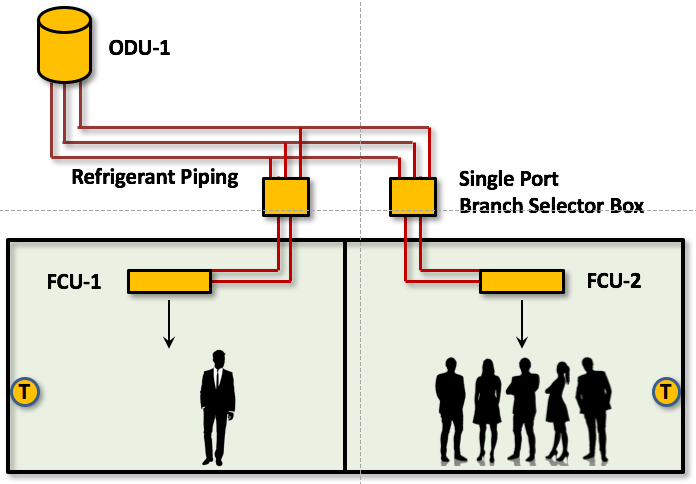
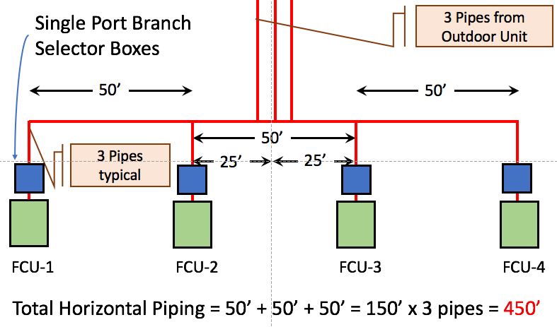
With a single port branch selector box, three main pipes are run from the VRF outdoor unit with three pipe branches to each single port branch selector box, and then on to the fan coils with two pipes. Many zones can be fed from a VRF multiport selector box versus just a single zone being fed from a single port branch selector box.

VRF Selector Box Location and Total Lengths of Piping

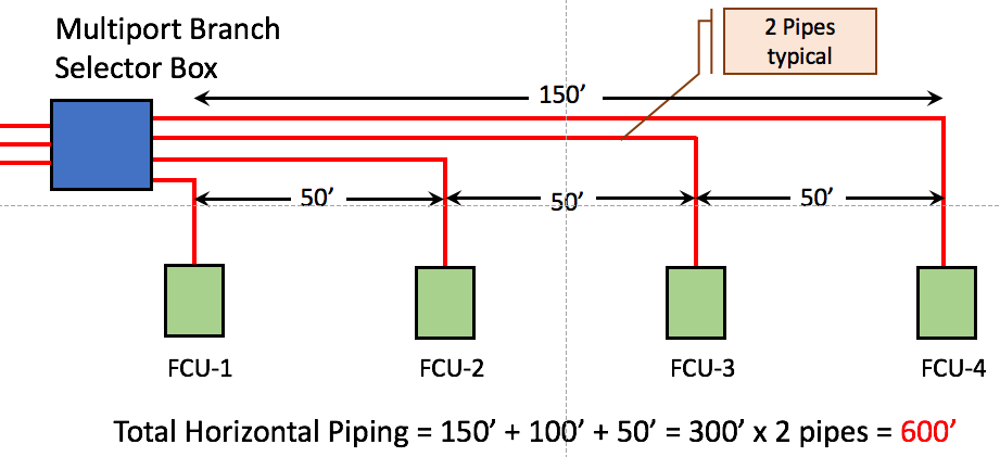
(VRF Multiport Box Condition #1) If the Multiport branch selector box is located at one end of a run with all the fan coils in front of it, then the total length of VRF Refrigerant piping will be substantially more, up to 100% more in some cases over that of a centered multipart or VRF single port selector box layout.

VRF Multi Port Branch Selector Box

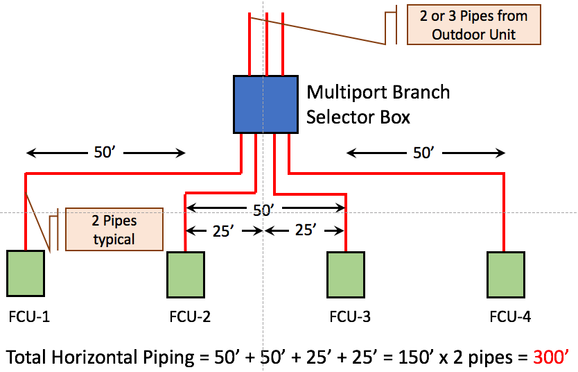
(VRF Multiport Box Condition #2) If the Multiport branch selector box is halfway between the outer fan coils with other fan coils between also equal distances from the multiport box, than the total piping will be close to what a single port box layout would have. This means having a fan coil on the right the same distance as a fan coil on the left side would match the same total length as a single port box layout or less depending on the location of the boxes in between the two ends.

VRF HVAC Multi Port Branch Selector Box

(VRF Single Port Box Condition #3) If the Single Port branch selector box is installed at each fan coil than the total VRF Refrigerant piping length will be between the two multiport selector box options above.

VRF HVAC Single Port Branch Selector Box

We all that said, your VRF manufacturer’s representative should assist, if not provide you with the most optimal layout and system choice for your particular project requirements.

Distance of VRF Refrigerant Piping Runs

Because of ASHRAE 15 and the restrictions on the amount of refrigerant allowed in the system based on room size, piping lengths become a factor. The longer the piping runs, the more refrigerant required, hence the larger the required minimum occupied space being served. With a multiport branch selector box the optimal location would most likely be the middle of the zone being served, that way downstream piping is minimized or optimized for length.

VRF in a Senior Facility

Depending on the type of facility and the availability of space to locate the branch selector boxes, either multiport or single port branch selectors may make a better choice. On my current project which is a large senior facility, the attic above the ceiling in the corridor lacks enough room for the much larger multiport branch selector box.

This made the selection of single port branch selector boxes the best choice as the boxes would be in the tenant spaces, and all that was required above the corridor ceiling was the three main refrigerant pipes coming from the condenser. At each tenant space, there would be a Y-fitting for the branch pipe leading to the single port box. See our article on the construction difficulties of a VRF system in an existing Senior Living Facility.

Three Advantage & Disadvantages of VRF Single Port Selector Boxes

Advantages of a VRF Single Branch Port Selector Box

  1. In this example it reduced the amount of piping required. (Each project is different)
  2. Less space required for piping.
  3. A VRF Single port branch selector box is smaller than a multiport box.

Disadvantages of a VRF Single Port Branch Selector Box

  1. VRF single port branch selector boxes require additional electrical connections, one for each single port box as opposed to just one at the multiport selector box.
  2. Additional points of failure.
  3. Multiple locations required for service access if service is required.

Not all VRF manufacturers have a single port selector box. Checkout Daikin’s VRF single port branch selector boxes.

Remember each type of branch selector box has its application, and one is not necessarily better than the other, each project requires an separate analysis.

Please leave a comment below and let us know some of the challenges your VRF projects have experienced and how you overcame them. This will inform our readers of possible solutions to similar problems that they may be facing. As always, we appreciate your feedback and experience with VRF.

HVAC Estimating spreadsheet

Subscribe to our mailing list

* indicates required