


What are the difficulties of Installing a VRF system in a Senior Living Facility?
The difficulty with this VRF project is that the existing senior living facility is occupied. There are two buildings in this senior facility, one classified for independent residents, and the other for those needing assistance. Each building is three stories with long corridors. The existing system is comprised of window Air Conditioning units and hot water radiators. The corridors are currently unconditioned and are the subject of many resident complaints during the hot summer months.
VRF Engineering Challenges
VRF and ASHRAE 15
ASHRAE 15 limits the amount of refrigerant allowed in an occupied space, which will dictate the size of any one system. Since this isn’t classified as an institutional facility we can use the full amount allowed for R410A of 26 Lbs/ 1,000 Ft3 of space per ASHRAE 34. See article on VRF ASHRAE 15 for further explanation.
Project Construction Phases
The owner wants to do the project in two phases to match their financing and capital improvement budget. The first phase was to be the conditioning of the corridors where most of the complaints originated from, as the tenants already had window mounted air conditioners in their rooms.
The second phase would be the more difficult one of doing the dance around occupied senior tenant spaces to install the fan coils, condensate drain and controls. The project also included major renovations to the interior of the tenant spaces and the installation of a new fire sprinkler system. Total renovation budget is over $6,000,000, phased over several years.
Outdoor Unit Requires 50% Minimum Startup Load
Another important consideration when doing a phased project with a VRF system is that most require a minimum of a 50% load on the outdoor unit before you can start them up. Of course, after starting them up they can run at a much-reduced rate with the amazing energy saving aspect.
This provides a challenge for the phasing of the project and the relocation or disruption for the senior occupants as we would need at least half of the tenant spaces connected in order to start the system. This meant that we would need 50% of the tenant spaces connected in phase 1 or delay the startup of the outdoor unit until phase 2 of the project.
Single Port vs Multiport Branch Selector Boxes
Deciding on whether to use a VRF single port or multi-port branch selector box was made by the job conditions more so then any other aspect. The project conditions included, limited space above the corridor ceiling, in this case 6 inches because of the low floor to floor height and the need to share the space with lighting and the new fire sprinkler system.
The VRF multi-port branch selector box is much bigger than the single port box and would require furring down the ceiling; aesthetically unpleasing. The VRF multiport box would require multiple runs of refrigerant piping from the box to each tenant space, requiring much more attic space.
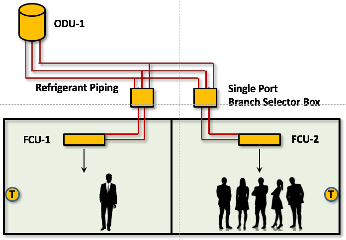 The decision was to use a VRF single port branch selector box after consulting with the client and the manufacture related to installing the piping without connecting the fan coils. The single port branch selector box saved the client some upfront cost until phase two of the project when they would be located within the tenant space, thus eliminating the space constraints of the corridor. This option only required us to run three main refrigerant pipes down the corridor with a Y-fitting at every location for a branch to the tenant space in phase two.
VRF System Oil Management
The manufactures concern was the management of the oil returning to the system, which requires avoiding any dead legs or capped piping branches which could potentially store oil in a pocket of the piping. The manufacture allowed the use of full-port Sporlan ball valves with taps at the Y-Branch fittings leading to the tenant spaces, with no piping extending off the mains. This would allow pressure testing, evacuating and charging the main pipes before installing any tenant fan coils, allowing the corridor renovation to be completed in phase one.
As part of phase one, we would install branch stubs into the tenant space for future connection. These stubs would not be charged, as they would be isolated from the main by the ball valves. Then during phase two, we would connect to these stubs and to the VRF single port branch selector box and tenant fan coil, pressure testing, evacuating and charging just the branch portion before opening the ball valve.
There is no way the tenants could stay in their rooms during construction unless they didn’t plan on coming out their rooms for the whole day, and the next two weeks that the corridor would be a mess of workers, ladders and tools.
Leading off with Asbestos Abatement
To make matters worse the corridor ceiling (Bottom of concrete slab above) was sprayed with asbestos in the old days, so this would need to be abated first. After the abatement, we would follow behind with our three main refrigerant pipes and Y-fittings.
The plan was to first do all the outdoor units including electrical, concrete pads and main refrigerant pipe up to where we penetrated the building before we started the tenant work. This would allow us to be ready as soon as we could get the mains run down the corridor and provide a 50% connected load.
Concerns of Management and Facility Staff
1. The management wanted to make the thermostats as simple as possible for the senior occupants to avoid unnecessary calls and complaints. This was easily accomplished by the options available for the face plate of the thermostat, which allowed for a version with as few buttons as possible, keeping it very simple.
2. They wanted to know how they would be notified if an error or VRF system alarm occurred. The main control panel has a feature that allows them to enter email addresses that will receive an automatic email alert on system alarm. The facility also wanted the Mechanical Company to receive the same notice and have a service vehicle in route as soon as the alarm message was received. This feature was also available within the control panel.
3. The senior facility was also concerned about the availability of trained service professional to respond quickly to any needed repairs or maintenance. This one will be based on your company’s service capabilities and their knowledge of VRF systems, for us this is not a problem as we have a large service fleet.
Summary of top 4 Challenges
1. ASHRAE 15
2. Requirement for 50% Load on Outdoor Unit
3. Occupied Senior Living Facility
4. Limited Attic Space above Corridor Ceiling.
Other Considerations
5. Simple thermostat for occupants
6. Fast response to system alarms.
The project description will be continued later in another project article.
Please leave a comment below and let us know some of the challenges of some of your VRF projects and how you overcame them. This will inform our readers of possible solutions to similar problems that they may be facing. As always, we appreciate your feedback and experience with VRF.


