VRF System Control Wiring
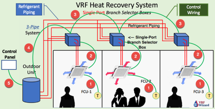
This VRF System control wiring is for a VRF VRV Heat Recovery System with single port branch selector boxes. The control wiring is very simple, it’s basically two 18 gauge wires that go from the thermostat to the fan coils (Wire #1), so that each zone will have a wire from the thermostat to the fan coil. One controller (Thermostat) can control more than one indoor fan coil if desired.
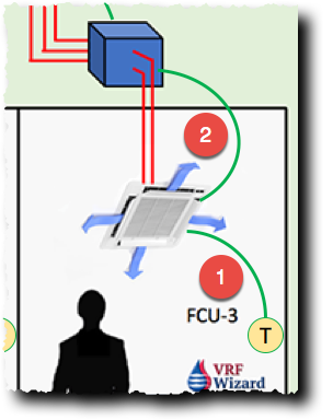
And then from the Indoor VRF Fan Coil to the single-port branch selector box (Wire #2), that will be a separate wire. Then the branch selector boxes are daisy chained together. So, you can just run one continuous wire jumping from box to box (Wire #3). You don’t have to run a homerun from each box separately to the outdoor unit. They daisy chain from each other in one long chain to the outdoor unit (Wire #4). And then from the VRF VRV outdoor unit to the control panel (Wire #5).
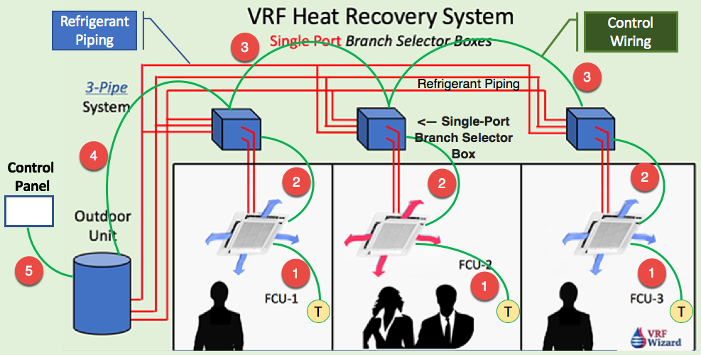

So, if you had multiple VRF VRV outdoor units you could daisy chain (Wire #6) them together and then go to the control panel (Wire #5). So, with a VRF VRV heat recovery system the VRF control wiring is very simple and if you are going to have a BACnet you can tie-in from the control panel, most of them have the capability, you’ll need to bring in an IP address and then your customer can remote access into the control panel and then from this control panel you can basically see and control each one of these fan coils you can lock out the capabilities of the thermostat if you wanted too. System status and alarms will show up on the main control panel.
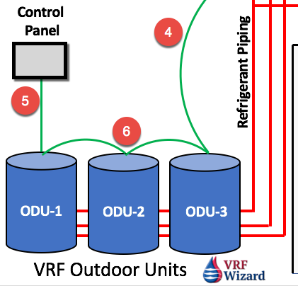

Each VRF VRV manufacture may have slightly different VRF System Control wiring layouts but they all have maximum Outdoor Units and Indoor Units that a control panel can be connected to without the addition of an expansion module or adapter (Wire #7). Daikin allows 64 maximum fan coils that you can put on one control panel. In order to expand the control panel capacity, you use adapters (Wire #7).
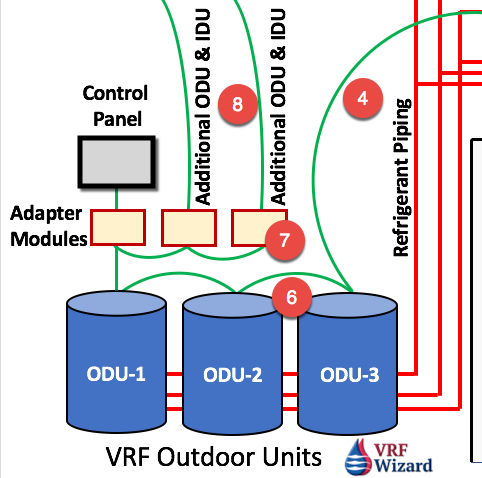

Each adapter allows you to connect another 10 Outdoor Units (Wire #8), with 64 addresses or 128 raw fan coils. Use adapters to add additional fan coils for large facilities or use multiple control panels. You daisy chain the adapters (Wire #7) together and then you go to the control panel. Check the VRF VRV manufacture that you’re using for their control wiring requirements, this one is from Daikin.
You can also watch the video of the VRF System Controls Wiring on Youtube.
Leave us a comment. What VRF System Control Wiring do you normally install and how does the wiring differ from this?
How to Calculate Cooling Loads.


